Difference between revisions of "DurangoMazatlanHighwayTour"
| (27 intermediate revisions by the same user not shown) | |||
| Line 1: | Line 1: | ||
<div style="font-size: 25px; text-align: center;"> | <div style="font-size: 25px; text-align: center;"> | ||
| − | + | Tour de la carretera Durango-Mazatlán<br /> | |
Durango-Mazatlán Highway Tour<br /> | Durango-Mazatlán Highway Tour<br /> | ||
</div> | </div> | ||
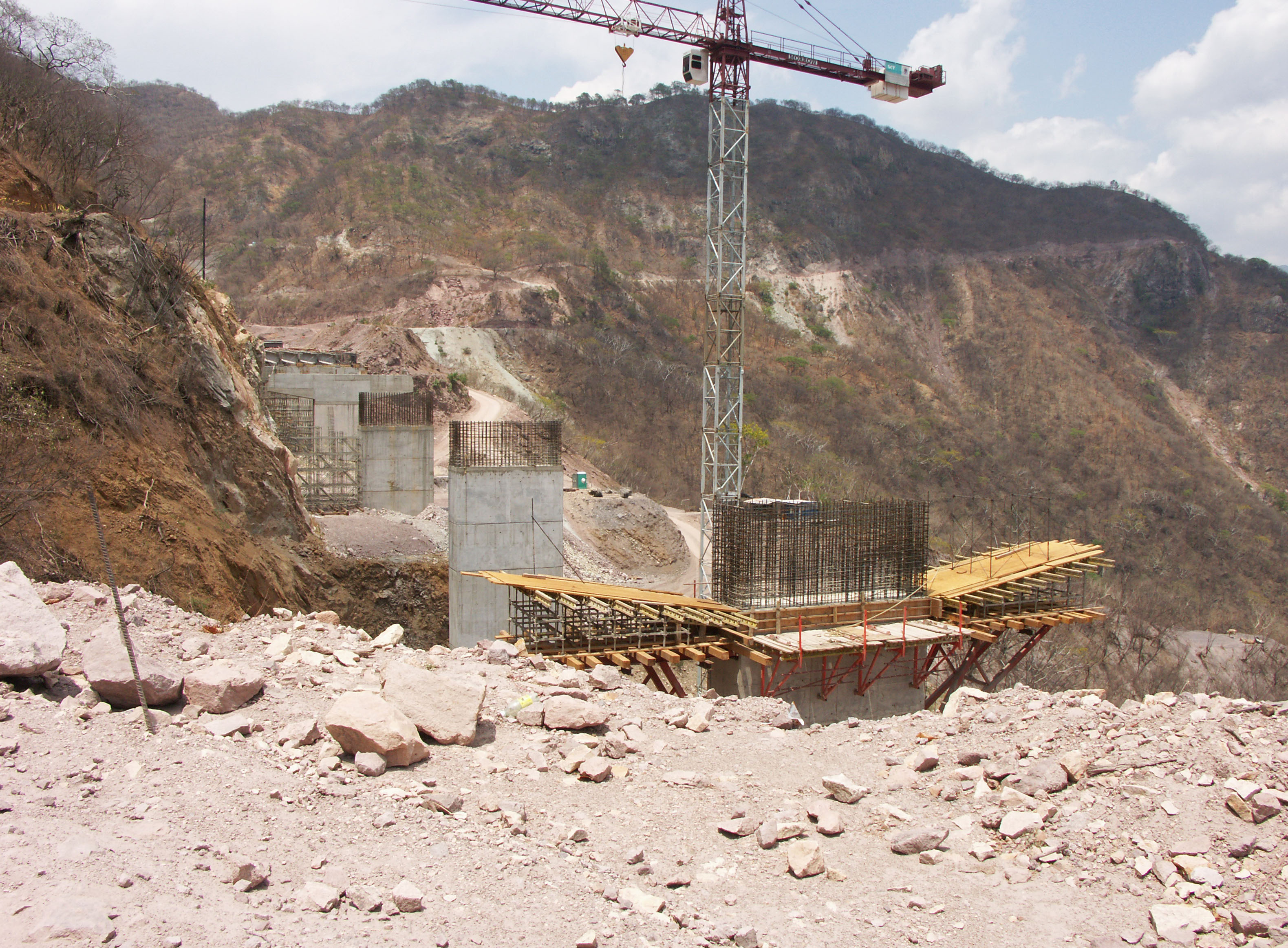
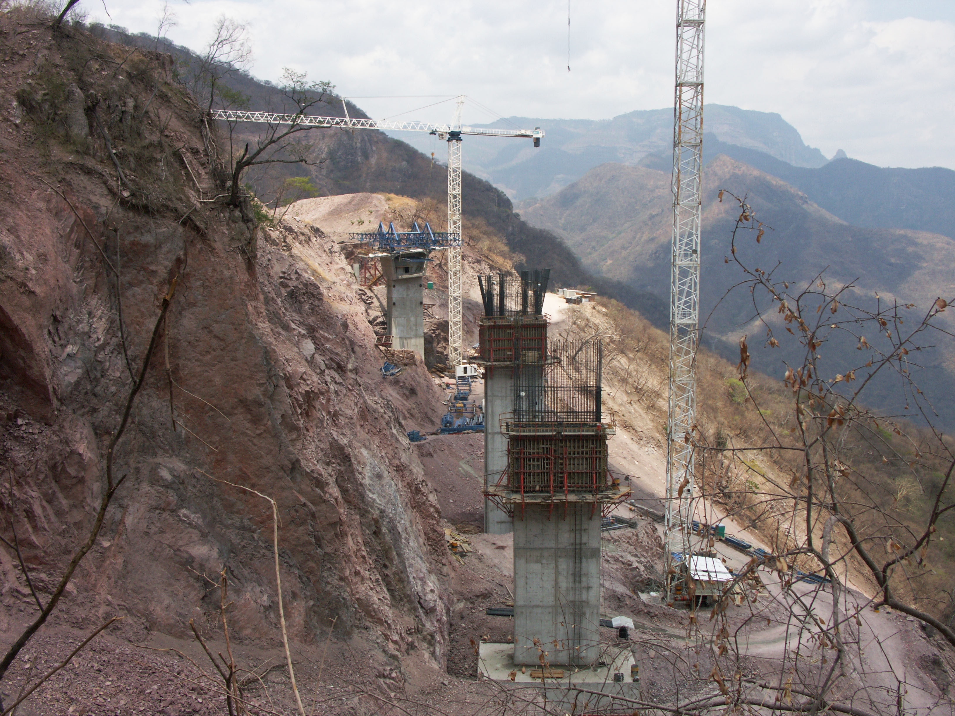
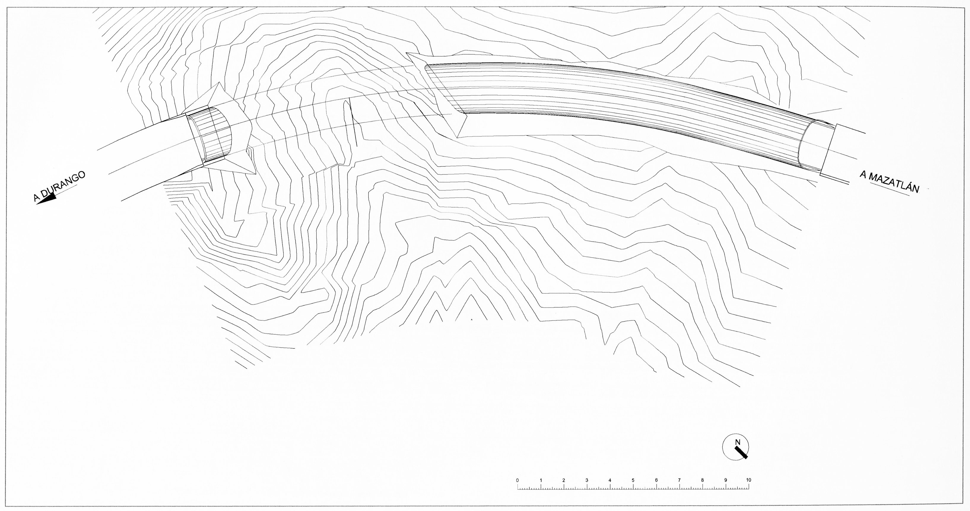
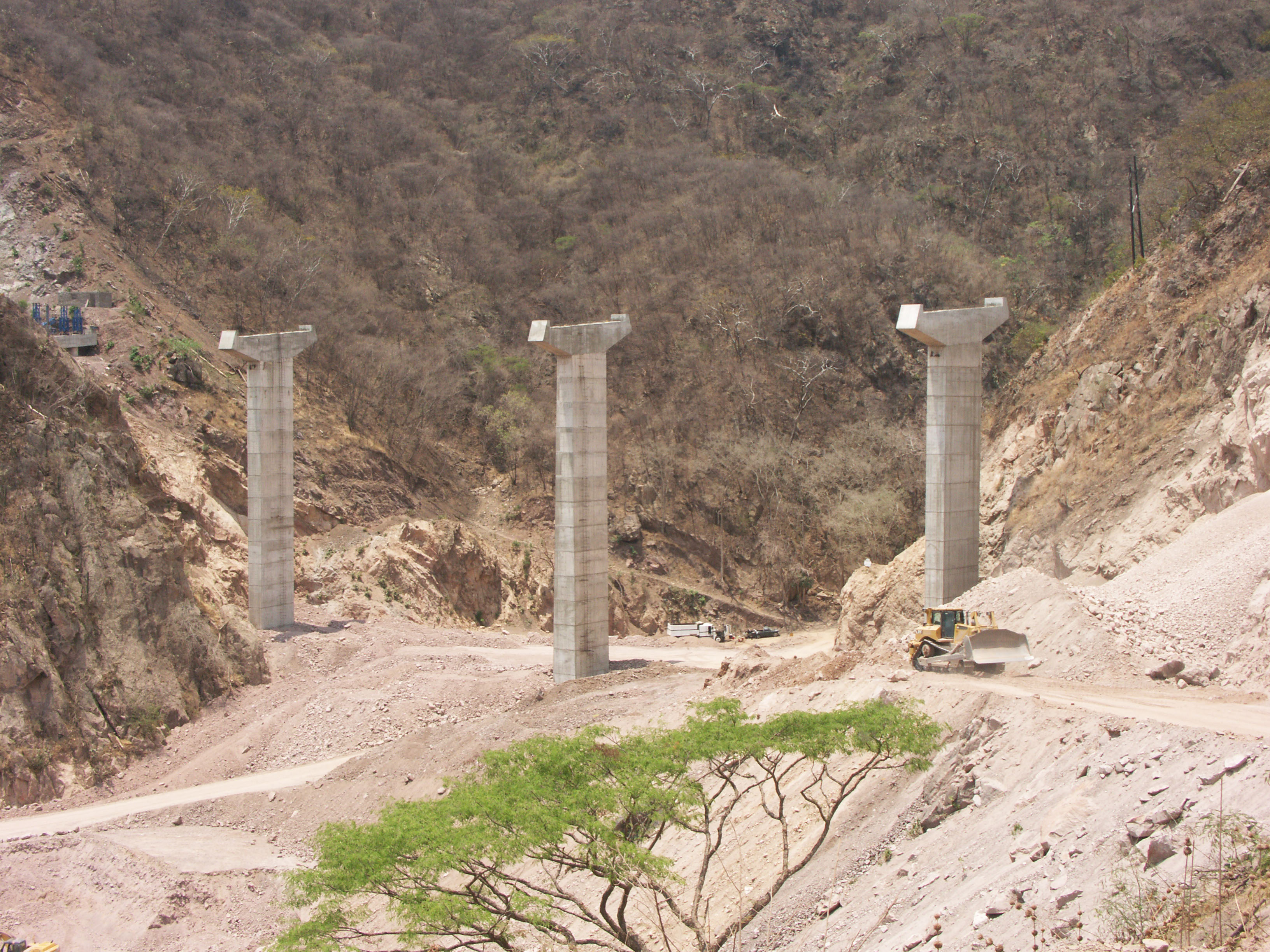
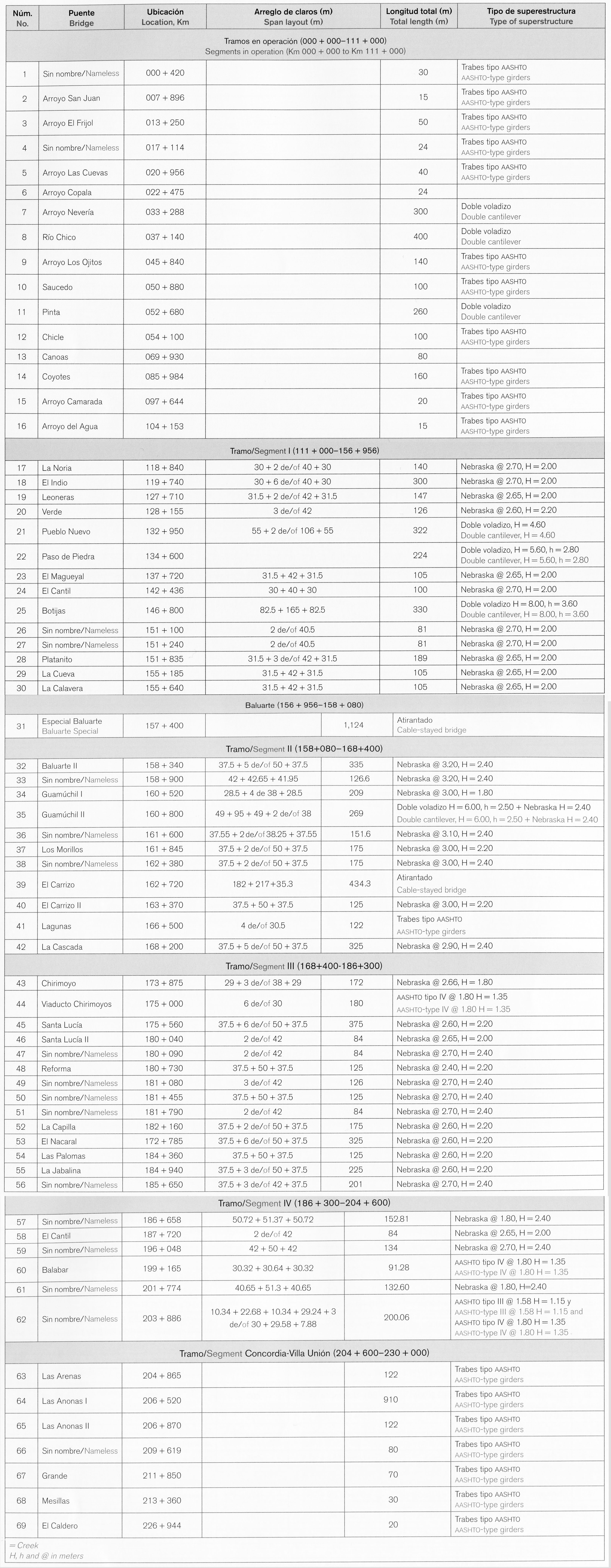
| − | El siguiente es un grupo selecto de imágenes tomadas durante | + | El siguiente es un grupo selecto de imágenes tomadas durante una visita en junio de 2012 a la porción central de la carretera Durango-Mazatlán, acompañado del Ing. Margarito Contreras de grupo TRIADA, así como imágenes de la SCT. Este tour se centró en aproximadamente 25 de los puentes más grandes de la carretera, con un énfasis especial en los claros de los 94 kilómetros centrales entre El Salto y Concordia, que finalmente serán abiertos al tráfico en el verano de 2013. |
| − | La gran mayoría de los puentes | + | La gran mayoría de los 69 puentes son de tipo Nebraska, con claros de vigas de concreto. Los ocho más grandes puentes viga son en ménsula (viga voladiza), mientras que los 2 cruces más largos y altos son atirantados. La carretera de 230 kilómetros también tiene 61 túneles, incluyendo El Sinaloense de 2.8 kilómetros. |
| − | The following is a select group of images taken during a June, 2012 visit to the central portion of the Durango-Mazatlán highway as well as images from the SCT. This construction tour focused on approximately 25 of the largest bridges on the highway with a special emphasis on the spans of the central 94 kilometers between El Salto and Concordia that will finally be open to traffic in the summer of 2013. | + | The following is a select group of images taken during a June, 2012 visit to the central portion of the Durango-Mazatlán highway, accompanied by engineer Margarito Contreras of grupo TRIADA, as well as images from the SCT. This construction tour focused on approximately 25 of the largest bridges on the highway with a special emphasis on the spans of the central 94 kilometers between El Salto and Concordia that will finally be open to traffic in the summer of 2013. |
The vast majority of the 69 bridges are Nebraska-type concrete girder spans. The eight largest beam bridges are double cantilever while the 2 longest and highest crossings are cable stayed. The 230 kilometer highway also has 61 tunnels including the 2.8 kilometer El Sinaloense tunnel. | The vast majority of the 69 bridges are Nebraska-type concrete girder spans. The eight largest beam bridges are double cantilever while the 2 longest and highest crossings are cable stayed. The 230 kilometer highway also has 61 tunnels including the 2.8 kilometer El Sinaloense tunnel. | ||
| Line 18: | Line 18: | ||
| + | [[File:Durango-MazatlanMap.jpg|850px|center]] | ||
| + | |||
| + | |||
| + | <div style="font-size: 25px; text-align: center;"> | ||
| + | Puentes en los kilómetros 30-40<br /> | ||
| + | </div> | ||
[[File:DurangoHwyKm30-40.jpg|750px|center]] | [[File:DurangoHwyKm30-40.jpg|750px|center]] | ||
| − | + | ||
[[File:NeveriasBridge_copy.jpg|750px|center]] | [[File:NeveriasBridge_copy.jpg|750px|center]] | ||
| − | Puente Neverías en el kilómetro 33. | + | Puente Neverías en el kilómetro 33. Su calzada está a 107 metros de altura y soporta un vano central de 140 metros. |
The Neverías Bridge deck is 107 meters high and supports a central span of 140 meters.Image by Eric Sakowski / HighestBridges.com | The Neverías Bridge deck is 107 meters high and supports a central span of 140 meters.Image by Eric Sakowski / HighestBridges.com | ||
| Line 29: | Line 35: | ||
[[File:Riochico06.jpg|750px|center]] | [[File:Riochico06.jpg|750px|center]] | ||
| − | Puente | + | Puente Río Chico en el kilómetro 37. Su calzada está a 120 metros de altura y soporta un vano central de 140 metros. |
The Rio Chico Bridge deck is 120 meters high and supports a central span of 140 meters. Image courtesy of Héctor S. Ovalle Mendivil / Coconal | The Rio Chico Bridge deck is 120 meters high and supports a central span of 140 meters. Image courtesy of Héctor S. Ovalle Mendivil / Coconal | ||
| + | <div style="font-size: 25px; text-align: center;"> | ||
| + | Puentes en los kilómetros 50-55<br /> | ||
| + | </div> | ||
[[File:DurangoHwyKm50-55.jpg|750px|center]] | [[File:DurangoHwyKm50-55.jpg|750px|center]] | ||
| − | |||
| Line 43: | Line 51: | ||
[[File:LaPintaBridge_copy.jpg|750px|center]] | [[File:LaPintaBridge_copy.jpg|750px|center]] | ||
| − | Puente La Pinta en el kilómetro 53. | + | Puente La Pinta en el kilómetro 53. El puente tiene a 70 metros de altura. |
The Pinta Bridge is 70 meters high. Image by Eric Sakowski / HighestBridges.com | The Pinta Bridge is 70 meters high. Image by Eric Sakowski / HighestBridges.com | ||
| Line 50: | Line 58: | ||
[[File:ElChicleBridge3_copy.jpg|750px|center]] | [[File:ElChicleBridge3_copy.jpg|750px|center]] | ||
Puente El Chicle en el kilómetro 54. Image by Eric Sakowski / HighestBridges.com | Puente El Chicle en el kilómetro 54. Image by Eric Sakowski / HighestBridges.com | ||
| + | |||
| + | |||
| + | <div style="font-size: 25px; text-align: center;"> | ||
| + | Puentes en los kilómetros 68-88<br /> | ||
| + | </div> | ||
| + | [[File:DurangoHwyKm70-86.jpg|750px|center]] | ||
[[File:RioCanoasBridge_copy.jpg|750px|center]] | [[File:RioCanoasBridge_copy.jpg|750px|center]] | ||
| − | Puente | + | Puente Río Canoas en el kilómetro 70. Image by Eric Sakowski / HighestBridges.com |
[[File:CoyotesBridge.jpg|750px|center]] | [[File:CoyotesBridge.jpg|750px|center]] | ||
Puente Coyotes en el kilómetro 86. Image by SCT | Puente Coyotes en el kilómetro 86. Image by SCT | ||
| + | |||
| + | |||
| + | <div style="font-size: 25px; text-align: center;"> | ||
| + | Puentes en los kilómetros 117-130<br /> | ||
| + | </div> | ||
| + | [[File:DurangoHwyKm118-130.jpg|750px|center]] | ||
[[File:LaNoria&ElIndio.jpg|450px|center]] | [[File:LaNoria&ElIndio.jpg|450px|center]] | ||
| − | + | Puentes La Noria y El Indio en el kilómetro 119. Image by SCT | |
[[File:ElIndioAerial.jpg|750px|center]] | [[File:ElIndioAerial.jpg|750px|center]] | ||
| − | Puente El Indio. | + | Puente El Indio. El puente cuenta con 8 claros: uno de 30, 6 de 40 y uno de 30 metros. Image by SCT |
| Line 73: | Line 93: | ||
[[File:DurangoHwyConstKm127.jpg|470px|center]] | [[File:DurangoHwyConstKm127.jpg|470px|center]] | ||
| − | + | Principios de la construcción de la carretera a la altura del kilómetro 127. | |
Early construction of highway at kilometer 127. Image by SCT | Early construction of highway at kilometer 127. Image by SCT | ||
| Line 79: | Line 99: | ||
[[File:LeoneraI&IItunnels.jpg|460px|center]] | [[File:LeoneraI&IItunnels.jpg|460px|center]] | ||
| − | Túnel Leonera I y II en el kilómetro | + | Túnel Leonera I y II en el kilómetro 127. |
| − | Con 18,000 metros de túnel, | + | Túneles Leonera I y II en el kilómetro 127. |
| + | Con 18,000 metros de túnel, ¡la nueva carretera Durango-Mazatlán tendrá más kilómetros de túneles carreteros que los que se han construido en toda la historia de México! | ||
With 18,000 meters of tunnel, the new Durango-Mazatlan highway will have more kilometers of road tunnel then have been built in the entire course of Mexico's history! Image by SCT | With 18,000 meters of tunnel, the new Durango-Mazatlan highway will have more kilometers of road tunnel then have been built in the entire course of Mexico's history! Image by SCT | ||
| Line 91: | Line 112: | ||
[[File:LeonerasBridge_copy.jpg|750px|center]] | [[File:LeonerasBridge_copy.jpg|750px|center]] | ||
| − | Puente Leoneras. | + | Puente Leoneras. El puente cuenta con 4 claros: uno de 31.5, 2 de 42 y uno de 31.5 metros. En el primer plano, la carretera se apoya en un relleno de grava detenido por un muro de concreto. |
In the foreground the road will be supported on a gravel fill retained by a concrete wall. Image by Eric Sakowski / HighestBridges.com | In the foreground the road will be supported on a gravel fill retained by a concrete wall. Image by Eric Sakowski / HighestBridges.com | ||
| Line 97: | Line 118: | ||
[[File:VerdeBridge_copy.jpg|750px|center]] | [[File:VerdeBridge_copy.jpg|750px|center]] | ||
| − | Puente Verde en el kilómetro 128. | + | Puente Verde en el kilómetro 128. El puente cuenta con 3 claros de 42 metros. Image by Eric Sakowski / HighestBridges.com |
[[File:LosAlacranes&ChavariaNuevoIIItunnels_copy.jpg|750px|center]] | [[File:LosAlacranes&ChavariaNuevoIIItunnels_copy.jpg|750px|center]] | ||
| − | + | Túneles Los Alacranes y Chavaria Nuevo III en el kilómetro 129. Image by Eric Sakowski / HighestBridges.com | |
| + | <div style="font-size: 25px; text-align: center;"> | ||
| + | Puentes en los kilómetros 130-140<br /> | ||
| + | </div> | ||
[[File:DurangoHwyKm130-140Skyscrapercity.jpg|750px|center]] | [[File:DurangoHwyKm130-140Skyscrapercity.jpg|750px|center]] | ||
| − | |||
[[File:PuebloNuevoAerial.jpg|750px|center]] | [[File:PuebloNuevoAerial.jpg|750px|center]] | ||
| − | Puente Pueblo Nuevo en el kilómetro 133. | + | Puente Pueblo Nuevo en el kilómetro 133. El puente cuenta con 4 claros: uno de 55, 2 de 106 y uno de 55 metros. Su altura es de 114 metros. |
The height is 114 meters. Image by SCT | The height is 114 meters. Image by SCT | ||
| Line 142: | Line 165: | ||
| + | <div style="font-size: 25px; text-align: center;"> | ||
| + | Puentes en los kilómetros 135 - 148<br /> | ||
| + | </div> | ||
[[File:DurangoHwyKm135-148Skyscrapercity.jpg|750px|center]] | [[File:DurangoHwyKm135-148Skyscrapercity.jpg|750px|center]] | ||
| − | |||
[[File:ElMagueyalBridge_copy.jpg|750px|center]] | [[File:ElMagueyalBridge_copy.jpg|750px|center]] | ||
| − | Puente El Magueyal en el kilómetro 137. | + | Puente El Magueyal en el kilómetro 137. El puente cuenta con 3 claros de 31.5, 42 y 31.5 metros. Image by Eric Sakowski / HighestBridges.com |
| Line 163: | Line 188: | ||
[[File:CantilSatellite.jpg|750px|center]] | [[File:CantilSatellite.jpg|750px|center]] | ||
| − | + | Imagen satelital del puente El Cantil. | |
| Line 175: | Line 200: | ||
[[File:ElFrijolarTunnel.jpg|460px|center]] | [[File:ElFrijolarTunnel.jpg|460px|center]] | ||
| − | + | Túneles El Frijolar y Tortuga en el kilómetro 145. La construcción temprana del Puente Botijas se puede ver enfrente de la entrada del túnel El Frijolar. | |
Early construction of Botijas Bridge can be seen in front of the tunnel entrance of El Frijolar. Image by SCT | Early construction of Botijas Bridge can be seen in front of the tunnel entrance of El Frijolar. Image by SCT | ||
| Line 181: | Line 206: | ||
[[File:ElFrijolarDiagram.jpg|650px|center]] | [[File:ElFrijolarDiagram.jpg|650px|center]] | ||
| − | El Frijolar | + | Entrada del túnel El Frijolar. Image by SCT |
[[File:ElFrijolarDiagram2.jpg|650px|center]] | [[File:ElFrijolarDiagram2.jpg|650px|center]] | ||
| − | + | Diagrama del anclaje en roca del túnel El Frijolar pared de roca ancla. | |
El Frijolar tunnel rock anchor diagram. Image by SCT | El Frijolar tunnel rock anchor diagram. Image by SCT | ||
| Line 191: | Line 216: | ||
[[File:BotijasBridge2_copy.jpg|750px|center]] | [[File:BotijasBridge2_copy.jpg|750px|center]] | ||
| − | Puente Botijas en el kilómetro 146. | + | Puente Botijas en el kilómetro 146. El puente cuenta con 3 claros de 82.5, 165 y 82.5 metros. Image by Eric Sakowski / HighestBridges.com |
| Line 199: | Line 224: | ||
[[File:BotijasBridge15_copy.jpg|750px|center]] | [[File:BotijasBridge15_copy.jpg|750px|center]] | ||
| − | + | ¡Una familia disfruta del puente Botijas! Image by Eric Sakowski / HighestBridges.com | |
| Line 207: | Line 232: | ||
[[File:BotijasBridge23_copy.jpg|750px|center]] | [[File:BotijasBridge23_copy.jpg|750px|center]] | ||
| − | + | El puente Botijas tiene la longitud de claro más larga y es también el puente viga más alto de la carretera. | |
| Line 221: | Line 246: | ||
| + | <div style="font-size: 25px; text-align: center;"> | ||
| + | Puentes en los kilómetros 150 - 157<br /> | ||
| + | </div> | ||
[[File:DurangoHwyKm150-157Skyscrapercity.jpg|750px|center]] | [[File:DurangoHwyKm150-157Skyscrapercity.jpg|750px|center]] | ||
| − | |||
| Line 230: | Line 257: | ||
[[File:ElPlatanitoSatellite.jpg|750px|center]] | [[File:ElPlatanitoSatellite.jpg|750px|center]] | ||
| − | Puente Platanito | + | Imagen satelital del Puente Platanito. |
[[File:BaluarteTunnelDurangoPortal.jpg|600px|center]] | [[File:BaluarteTunnelDurangoPortal.jpg|600px|center]] | ||
| − | Una de las | + | Una de las portales de túneles más difíciles fue la entrada del túnel Baluarte en el lado de Durango. Un bloque de 20,000 toneladas cayó en el portal delantero, lo que obligó a los ingenieros a mover el portal de entrada 8 metros a la derecha, así como el uso de anclas de tensión de 25 metros de largo en un patrón escalonado de 5 x 5 metros en la ladera. |
One of the most difficult tunnel portals was the Durango entrance of the Baluarte tunnel. A 20,000 ton block crashed down at the front portal and required the engineers to move the portal entrance 8 meters to the right as well as using 25 meter long tension anchors in a staggered pattern of 5 x 5 meters on the slope. Image by SCT | One of the most difficult tunnel portals was the Durango entrance of the Baluarte tunnel. A 20,000 ton block crashed down at the front portal and required the engineers to move the portal entrance 8 meters to the right as well as using 25 meter long tension anchors in a staggered pattern of 5 x 5 meters on the slope. Image by SCT | ||
| Line 249: | Line 276: | ||
<div style="font-size: 25px; text-align: center;"> | <div style="font-size: 25px; text-align: center;"> | ||
Puente Baluarte - <br /> | Puente Baluarte - <br /> | ||
| − | + | ¡El puente más alto en la carretera Durango-Mazatlán!<br /> | |
</div> | </div> | ||
[[File:BaluarteBridge133_copy.JPG|450px|center]] | [[File:BaluarteBridge133_copy.JPG|450px|center]] | ||
| − | El gran puente Baluarte en el kilómetro 157. El más alto en el continente americano | + | El gran puente Baluarte en el kilómetro 157. El más alto en el continente americano, con una altura de 390 metros. Image by Eric Sakowski / HighestBridges.com |
| Line 262: | Line 289: | ||
[[File:BaluarteBuildings.jpg|750px|center]] | [[File:BaluarteBuildings.jpg|750px|center]] | ||
| − | + | Vivienda para los trabajadores y oficinas para la construcción del puente Baluarte. | |
Worker housing and headquarters for the Baluarte bridge construction. Image by SCT | Worker housing and headquarters for the Baluarte bridge construction. Image by SCT | ||
| Line 268: | Line 295: | ||
[[File:BaluarteLadderPier.jpg|350px|center]] | [[File:BaluarteLadderPier.jpg|350px|center]] | ||
| − | + | La pila 9 del puente Baluarte está a 140 metros de altura. Image by SCT | |
[[File:DevilsBackboneSign.jpg|650px|center]] | [[File:DevilsBackboneSign.jpg|650px|center]] | ||
| − | Signo | + | Signo del Espinazo del Diablo y la inauguración de la carretera antigua en 1960 con el presidente Adolfo López Mateos. |
Devil's Backbone sign & inauguration in 1960 with Presidente Adolfo López Mateos. Image by SCT | Devil's Backbone sign & inauguration in 1960 with Presidente Adolfo López Mateos. Image by SCT | ||
| Line 281: | Line 308: | ||
| + | <div style="font-size: 25px; text-align: center;"> | ||
| + | Puentes en los kilómetros 157 - 166<br /> | ||
| + | </div> | ||
[[File:DurangoHwyKm157-166.jpg|750px|center]] | [[File:DurangoHwyKm157-166.jpg|750px|center]] | ||
| − | |||
| Line 290: | Line 319: | ||
[[File:ElVaralTunnelStressDiagram.jpg|750px|center]] | [[File:ElVaralTunnelStressDiagram.jpg|750px|center]] | ||
| − | + | Modelado de malla y diagrama de esfuerzo de la masa de roca circundante al túnel El Varal. Para estimar el peso de una cuña de roca que podría deslizarse hacia el interior de un túnel y debe ser soportada por el revestimiento, los parámetros deben de ser calculados para la carga en puntos clave, la anchura del túnel, el peso de la roca, la cohesión del sistema de fracturas encima de puntos clave del túnel, la relación entre las tensiones horizontal y vertical, la profundidad del túnel y el ángulo de fricción encima de puntos clave del túnel. | |
Mesh modeling and stress diagram of the rock mass surrounding El Varal tunnel. To estimate the weight of a rock wedge that could slide towards the inside of a tunnel and must be supported by the lining, parameters must be calculated for rock surcharge at the key, the width of the tunnel, the unit weight of the rock, the cohesion of the fracture system immediately above the key of the tunnel, the ratio between horizontal and vertical stresses, the depth of the tunnel and the angle of friction immediately above the key of the tunnel. Image by SCT | Mesh modeling and stress diagram of the rock mass surrounding El Varal tunnel. To estimate the weight of a rock wedge that could slide towards the inside of a tunnel and must be supported by the lining, parameters must be calculated for rock surcharge at the key, the width of the tunnel, the unit weight of the rock, the cohesion of the fracture system immediately above the key of the tunnel, the ratio between horizontal and vertical stresses, the depth of the tunnel and the angle of friction immediately above the key of the tunnel. Image by SCT | ||
| Line 296: | Line 325: | ||
[[File:GuamuchilOnelBridge_copy.jpg|750px|center]] | [[File:GuamuchilOnelBridge_copy.jpg|750px|center]] | ||
| − | Puente Guamuchil I en el kilómetro 160. | + | Puente Guamuchil I en el kilómetro 160. El puente cuenta con 6 claros: uno 28.5, 4 de 38 y uno de 28.5 metros.Image by Eric Sakowski / HighestBridges.com |
[[File:GuamuchilBridge4_copy.jpg|750px|center]] | [[File:GuamuchilBridge4_copy.jpg|750px|center]] | ||
| − | Puente Guamúchil II en el kilómetro 160. | + | Puente Guamúchil II en el kilómetro 160. El puente cuenta con 5 claros de: 49, 95, 49 y 2 de 38 metros. Image by Eric Sakowski / HighestBridges.com |
[[File:GuamuchillFalseTunnelDiagram.jpg|750px|center]] | [[File:GuamuchillFalseTunnelDiagram.jpg|750px|center]] | ||
| − | Muchos de los túneles tienen secciones falsas que mantendrán a salvo de | + | Muchos de los túneles tienen secciones falsas que mantendrán la carretera a salvo de laderas inestables y inestables como el túnel de Guamuchil. |
Many of the tunnels have false sections that will keep the highway safe from unstable and steep slopes such as the Guamuchil tunnel. Image by SCT | Many of the tunnels have false sections that will keep the highway safe from unstable and steep slopes such as the Guamuchil tunnel. Image by SCT | ||
| Line 310: | Line 339: | ||
[[File:LosMorillosBridge5_copy.jpg|750px|center]] | [[File:LosMorillosBridge5_copy.jpg|750px|center]] | ||
| − | Puente Los Morillos en el kilómetro 161. | + | Puente Los Morillos en el kilómetro 161. El puente cuenta con 4 claros de: 37.5, 50, 50 y 37.5 metros. Image by Eric Sakowski / HighestBridges.com |
[[File:DurangoHwySigns.jpg|750px|center]] | [[File:DurangoHwySigns.jpg|750px|center]] | ||
| − | Vista en planta de las señales de tráfico para ser | + | Vista en planta de las señales de tráfico para ser colocadas entre los kilómetros 158 y 168, entre los puentes Baluarte y El Carrizo. |
Plan view of traffic signs to be placed between kilometers 158 and 168 between Baluarte and El Carrizo Bridges. Image by SCT | Plan view of traffic signs to be placed between kilometers 158 and 168 between Baluarte and El Carrizo Bridges. Image by SCT | ||
| Line 321: | Line 350: | ||
<div style="font-size: 25px; text-align: center;"> | <div style="font-size: 25px; text-align: center;"> | ||
Puente El Carrizo - <br /> | Puente El Carrizo - <br /> | ||
| − | Puente más | + | ¡El Puente con la pila más alta de la carretera Durango Mazatlán!<br /> |
</div> | </div> | ||
[[File:ElCarrizoDrawing_copy.jpg|750px|center]] | [[File:ElCarrizoDrawing_copy.jpg|750px|center]] | ||
| − | Con tanta atención en la construcción del Puente Baluarte, | + | Con tanta atención en la construcción del Puente Baluarte, los medios de comunicación no han prestado mucha atención al segundo puente atirantado de la quebrada El Carrizo ubicado a sólo 5 kilómetros al poniente. Con un mástil central y torre que se eleva a 226 metros, el puente El Carrizo es el más alto de la carretera y la segunda estructura de puente más alta de toda América del Norte después del Puente Mezcala. La estructura es sólo un metro más alta que la Torre Mayor en la Ciudad de México. |
| − | + | Diseño de la elevación del puente El Carrizo sobre una fotografía del área. | |
With so much attention on the construction of Baluarte Bridge, few in the media have given much attention to the second cable stayed crossing of the El Carrizo gorge located just 5 kilometers west. With a central pier and tower rising 226 meters, the El Carrizo Bridge is the tallest bridge on the highway and the second tallest bridge structure in all of North America after the Mezcala Bridge. The structure is just one meter higher then the Torre Mayor building in Mexico City. | With so much attention on the construction of Baluarte Bridge, few in the media have given much attention to the second cable stayed crossing of the El Carrizo gorge located just 5 kilometers west. With a central pier and tower rising 226 meters, the El Carrizo Bridge is the tallest bridge on the highway and the second tallest bridge structure in all of North America after the Mezcala Bridge. The structure is just one meter higher then the Torre Mayor building in Mexico City. | ||
| Line 340: | Line 369: | ||
[[File:ElCarrizoBridge36_copy.jpg|750px|center]] | [[File:ElCarrizoBridge36_copy.jpg|750px|center]] | ||
| − | El Carrizo fue diseñado originalmente como | + | El Carrizo fue diseñado originalmente como un puente viga de dos claros en voladizo, antes de ser rediseñado como un puente atirantado de un sólo mástil. El diseño actual tiene un vano central de 30 segmentos, cada uno con longitudes individuales de 8 metros y uno central de 12 metros donde la cubierta pasa a través de la torre. 28 de estos segmentos están conectados al mástil central por pares de tirantes. |
El Carrizo was originally designed as a two span cantilevered beam bridge before it was redesigned as a single tower cable stayed bridge. The current design has a central span of 30 segments, each with individual lengths of 8 meters and a central unit of 12 meters where the deck passes through the tower. 28 of these segments are connected to the central mast by a pair of stays. Image by Eric Sakowski / HighestBridges.com | El Carrizo was originally designed as a two span cantilevered beam bridge before it was redesigned as a single tower cable stayed bridge. The current design has a central span of 30 segments, each with individual lengths of 8 meters and a central unit of 12 meters where the deck passes through the tower. 28 of these segments are connected to the central mast by a pair of stays. Image by Eric Sakowski / HighestBridges.com | ||
| Line 350: | Line 379: | ||
<div style="font-size: 25px; text-align: center;"> | <div style="font-size: 25px; text-align: center;"> | ||
| − | + | Los puentes más altos de México y la Torre Mayor<br /> | |
</div> | </div> | ||
[[File:MezcalaTowerComparisonFinal.jpg|750px|center]] | [[File:MezcalaTowerComparisonFinal.jpg|750px|center]] | ||
| − | Más altos puentes de México y Torre Mayor diagram by Eric Sakowski / HighestBridges.com | + | Más altos puentes de México y Torre Mayor diagram by Eric Sakowski / HighestBridges.com and Skyscraperpage.com |
[[File:ElCarrizoBridge11_copy.jpg|750px|center]] | [[File:ElCarrizoBridge11_copy.jpg|750px|center]] | ||
| − | + | Pila II del puente El Carrizo. Image by Eric Sakowski / HighestBridges.com | |
| Line 371: | Line 400: | ||
[[File:ElCarrizoBridge27_copy.jpg|750px|center]] | [[File:ElCarrizoBridge27_copy.jpg|750px|center]] | ||
| − | + | ¡11 trabajadores cuelgan 200 metros por encima del cañón El Carrizo! | |
11 workers hang 200 meters above the canyon of El Carrizo! Image by Eric Sakowski / HighestBridges.com | 11 workers hang 200 meters above the canyon of El Carrizo! Image by Eric Sakowski / HighestBridges.com | ||
| Line 377: | Line 406: | ||
[[File:ElCarrizoSatelliteNew.jpg|750px|center]] | [[File:ElCarrizoSatelliteNew.jpg|750px|center]] | ||
| − | Puente El Carrizo | + | Imagen satelital del Puente El Carrizo. |
| − | [[File:DurangoHwyKm167-175Skyscrapercity.jpg|750px|center]] | + | <div style="font-size: 25px; text-align: center;"> |
| − | + | Puentes en los kilómetros 167 - 175 y el túnel Sinaloense<br /> | |
| + | </div> | ||
| + | [[File:DurangoHwyKm167-175Skyscrapercity.jpg|750px|center]]. | ||
[[File:LaCascadaBridge2_copy.jpg|750px|center]] | [[File:LaCascadaBridge2_copy.jpg|750px|center]] | ||
| − | Puente La Cascada en el kilómetro 168. | + | Puente La Cascada en el kilómetro 168. El puente cuenta con 7 claros: uno de 37.5, 5 de 50 y uno de 37.5 metros. Image by Eric Sakowski / HighestBridges.com |
[[File:CascadaSatellite.jpg|750px|center]] | [[File:CascadaSatellite.jpg|750px|center]] | ||
| − | Puente Cascada | + | Imagen satelital del Puente Cascada. |
<div style="font-size: 25px; text-align: center;"> | <div style="font-size: 25px; text-align: center;"> | ||
Túnel Sinaloenese - <br /> | Túnel Sinaloenese - <br /> | ||
| − | + | ¡El túnel más grande en la carretera Durango-Mazatlán!<br /> | |
</div> | </div> | ||
| Line 403: | Line 434: | ||
[[File:SinaloeneseDurangoPortal1.jpg|750px|center]] | [[File:SinaloeneseDurangoPortal1.jpg|750px|center]] | ||
| − | + | Portal del túnel Sinaloense. Image by SCT | |
[[File:SinaloeneseDurangoPortal2.jpg|750px|center]] | [[File:SinaloeneseDurangoPortal2.jpg|750px|center]] | ||
| − | + | Portal del túnel Sinaloense. Image by SCT | |
[[File:TunnelingProcess.jpg|650px|center]] | [[File:TunnelingProcess.jpg|650px|center]] | ||
| − | + | El efecto túnel básico.. Image by SCT | |
[[File:TunnelWallDrilling.jpg|450px|center]] | [[File:TunnelWallDrilling.jpg|450px|center]] | ||
| − | Las entradas del túnel | + | Las entradas del túnel pueden ser un punto problemático para la estabilidad de la roca, requiriendo el uso de anclas. Estos anclajes de fricción y tensión sostienen vigas de concreto que detienen masas rocosas de baja calidad. |
The tunnel entrances can be a problem spot for rock stability requiring the use of anchors. These friction and tension anchors hold concrete tie beams that can hold back poor quality rock masses. Image by SCT | The tunnel entrances can be a problem spot for rock stability requiring the use of anchors. These friction and tension anchors hold concrete tie beams that can hold back poor quality rock masses. Image by SCT | ||
| Line 433: | Line 464: | ||
[[File:TunnelExcavationDiagram.jpg|750px|center]] | [[File:TunnelExcavationDiagram.jpg|750px|center]] | ||
| − | La excavación del túnel se inicia | + | La excavación del túnel se inicia en su mitad superior. Sólo después de que los soportes del techo han sido instalados, la mitad inferior del túnel puede ser excavada. |
Tunnel excavation starts with the top half of the tunnel. After the roof supports are installed the bottom half of the tunnel is then dug out. Image by SCT | Tunnel excavation starts with the top half of the tunnel. After the roof supports are installed the bottom half of the tunnel is then dug out. Image by SCT | ||
| Line 447: | Line 478: | ||
[[File:TunnelExcavationSupports.jpg|750px|center]] | [[File:TunnelExcavationSupports.jpg|750px|center]] | ||
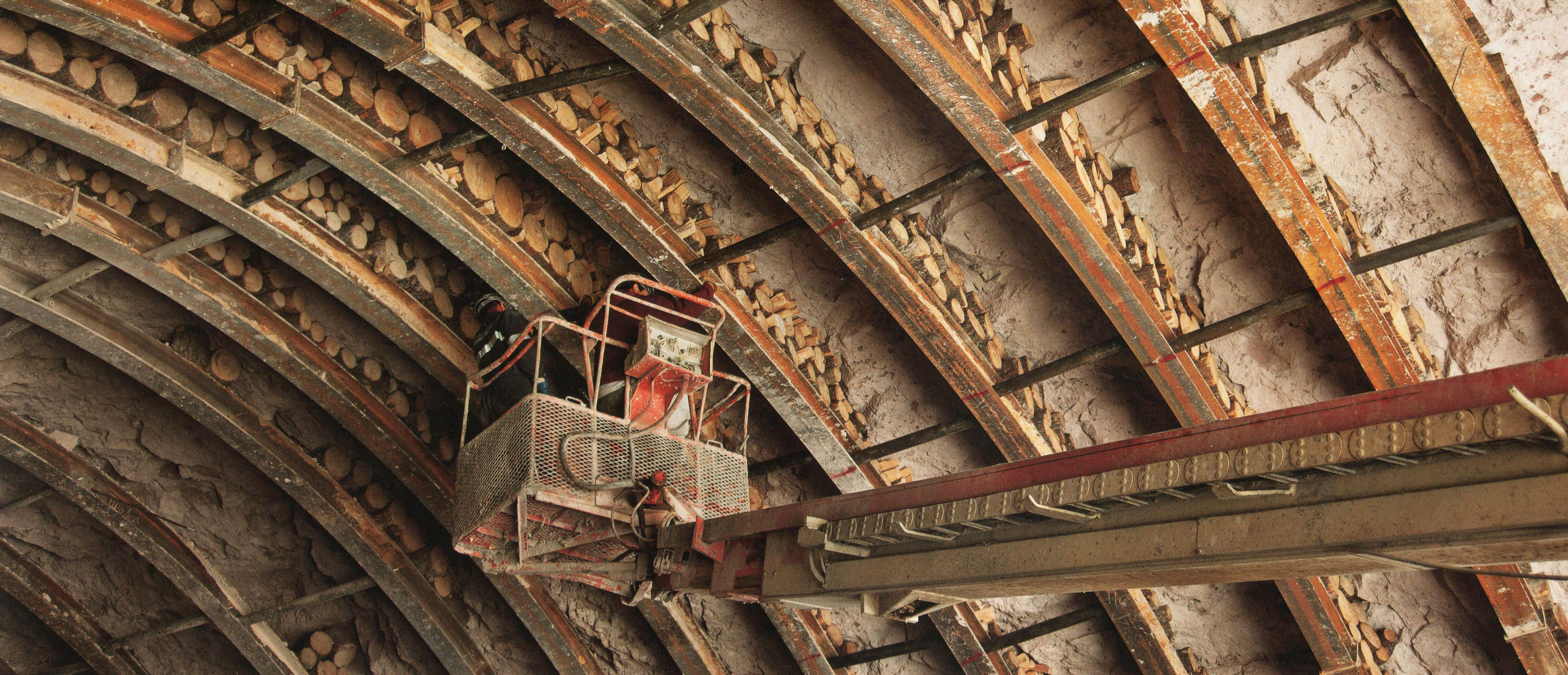
| − | + | En algunas secciones del túnel, se usan maderos entre el soporte de acero y la roca provisionalmente, antes rellenar el hueco con concreto. | |
For some sections of tunnel, timber is used between the steel support and the rock before concrete fills in the gap. Image by SCT | For some sections of tunnel, timber is used between the steel support and the rock before concrete fills in the gap. Image by SCT | ||
| Line 453: | Line 484: | ||
[[File:DrillHoles.jpg|650px|center]] | [[File:DrillHoles.jpg|650px|center]] | ||
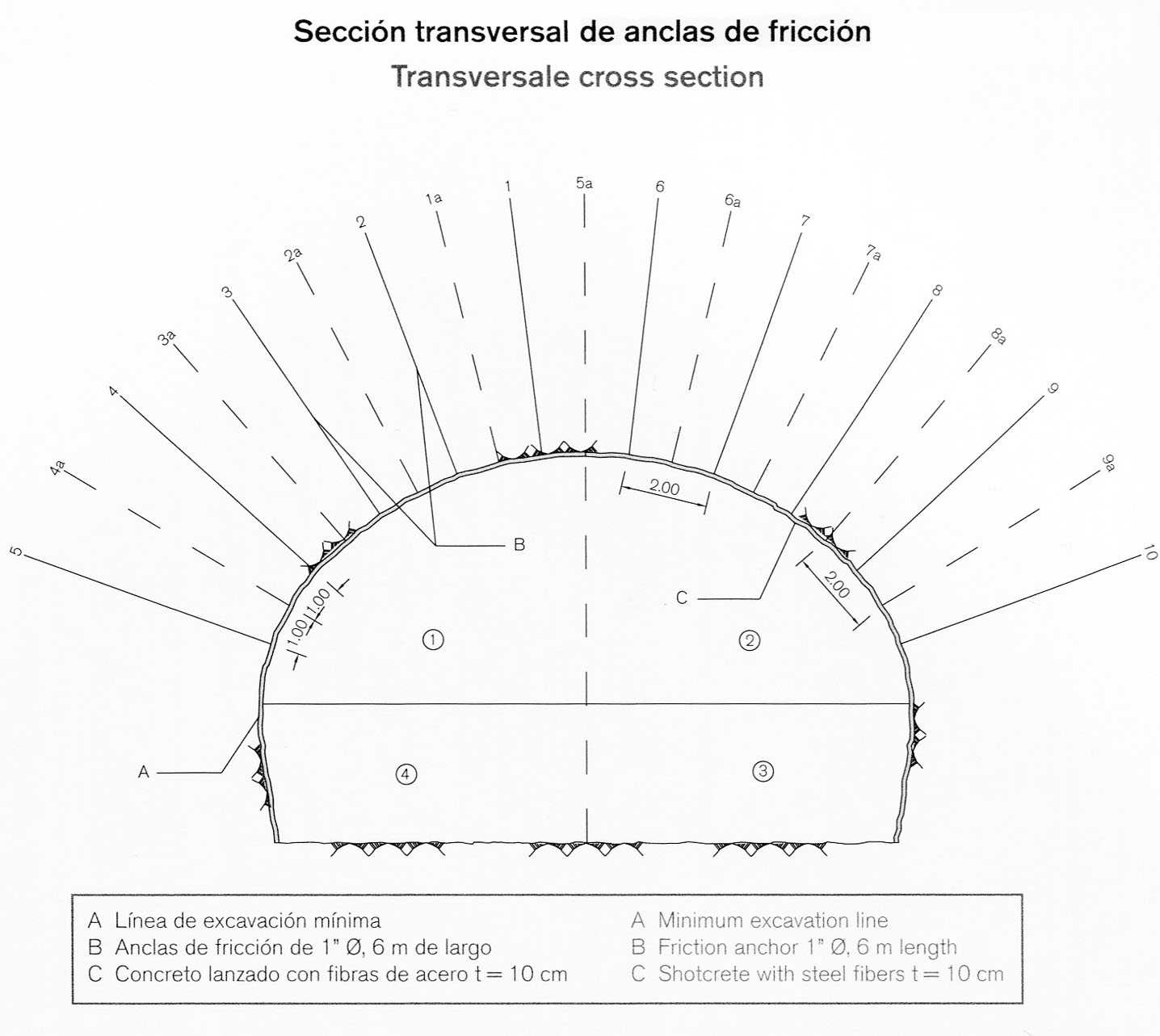
| − | + | Los anclajes de fricción se usan para estabilizar la roca encima de ciertas secciones de túnel. | |
Friction anchors are used to stabilize the rock above certain sections of tunnel. Image by SCT | Friction anchors are used to stabilize the rock above certain sections of tunnel. Image by SCT | ||
| Line 459: | Line 490: | ||
[[File:FrictionAnchors.jpg|480px|center]] | [[File:FrictionAnchors.jpg|480px|center]] | ||
| − | En la vista | + | En la vista de arriba del túnel Sinaloense se puede ver el uso de anclajes de fricción en una sección y de soportes de acero en otra. El uso de varios tipos de soporte de túnel basado en el tipo de roca se desarrolló en Austria. |
In the above view of the Sinaloenese tunnel you can see the use of friction anchors on one section and steel supports on another. This use of several types of tunnel supports based on the rock type was developed in Austria. Image by SCT | In the above view of the Sinaloenese tunnel you can see the use of friction anchors on one section and steel supports on another. This use of several types of tunnel supports based on the rock type was developed in Austria. Image by SCT | ||
| Line 471: | Line 502: | ||
[[File:SinaloeneseTunnel2_copy.jpg|750px|center]] | [[File:SinaloeneseTunnel2_copy.jpg|750px|center]] | ||
| − | + | Los encofrados utilizados para el revestimiento final de concreto del túnel deben ajustarse a las alturas cambiantes, así como a curvas que deben ser suaves y consistentes en toda la longitud del túnel. Se fabricaron un total de 12 encofrados de acero. Tres fueron compatibles para la construcción de los túneles de 4 carriles, mientras que nueve se utilizaron para el resto de los túneles de 2 carriles. | |
Formworks used for the final concrete tunnel lining must adjust to changing heights as well as curves that must be smooth and consistent for the entire length of the tunnel. There were a total of 12 steel formworks made. Three were compatible for the construction of the 4-lane tunnels while nine were used for the rest of the 2-lane tunnels. Image by Eric Sakowski / HighestBridges.com | Formworks used for the final concrete tunnel lining must adjust to changing heights as well as curves that must be smooth and consistent for the entire length of the tunnel. There were a total of 12 steel formworks made. Three were compatible for the construction of the 4-lane tunnels while nine were used for the rest of the 2-lane tunnels. Image by Eric Sakowski / HighestBridges.com | ||
| Line 477: | Line 508: | ||
[[File:SinaloeneseDiagrams.jpg|750px|center]] | [[File:SinaloeneseDiagrams.jpg|750px|center]] | ||
| − | Para el estudio de la roca | + | Para el estudio de la roca muy por debajo del recorrido del túnel Sinaloense, se adoptaron sondeos electromagnéticos de frecuencia, aplicando el método magneto-telúrico de fuente controlada. Además, se aplicó un sistema de refracción sísmica, detectando vibraciones de 12 diferentes geófonos que leen las ondas sísmicas generadas en la tierra. Diez diferentes perforaciones también se realizaron para determinar la calidad de la roca a diferentes profundidades. |
To study the rock deep below the path of the Sinaloense tunnel, Electromagnetic Frequency Soundings were adopted applying the Controlled Source Audio Magneto Telluric method. In addition, a seismic refraction system was applied, detecting vibrations from 12 different geophones that read the seismic waves generated into the ground. Ten different borings were also made to determine rock quality at different depths. Image by SCT | To study the rock deep below the path of the Sinaloense tunnel, Electromagnetic Frequency Soundings were adopted applying the Controlled Source Audio Magneto Telluric method. In addition, a seismic refraction system was applied, detecting vibrations from 12 different geophones that read the seismic waves generated into the ground. Ten different borings were also made to determine rock quality at different depths. Image by SCT | ||
| Line 483: | Line 514: | ||
[[File:SinaloenesePlasticStress.jpg|750px|center]] | [[File:SinaloenesePlasticStress.jpg|750px|center]] | ||
| − | Diagramas de tensión para dos secciones | + | Diagramas de tensión para dos diferentes secciones del túnel Sinaloense. |
Stress diagrams for two different sections of the Sinaloense tunnel. Image by SCT | Stress diagrams for two different sections of the Sinaloense tunnel. Image by SCT | ||
| Line 489: | Line 520: | ||
[[File:TunnelLiningImage.jpg|750px|center]] | [[File:TunnelLiningImage.jpg|750px|center]] | ||
| − | La última capa | + | La última capa del revestimiento de un túnel consta de una membrana conocida como geotextil, una tela no tejida de fibra de poliéster. Esta membrana recoge las filtraciones de agua de la roca y las transmite al drenaje en la parte inferior del túnel. |
The final layer of tunnel lining consists of a membrane known as geotextile, a non-woven polyester fiber fabric. This membrane collects water seepage from the rock and conveys it to the drainage works at the bottom of the tunnel. Image by SCT | The final layer of tunnel lining consists of a membrane known as geotextile, a non-woven polyester fiber fabric. This membrane collects water seepage from the rock and conveys it to the drainage works at the bottom of the tunnel. Image by SCT | ||
| Line 503: | Line 534: | ||
[[File:DrainageDiagram.jpg|750px|center]] | [[File:DrainageDiagram.jpg|750px|center]] | ||
| − | Diagrama | + | Diagrama del drenaje de agua en la parte inferior del túnel. |
| − | Diagram of water drainage at bottom of the tunnel. Image by SCT | + | Diagram of water drainage at the bottom of the tunnel. Image by SCT |
[[File:TunnelLights.jpg|750px|center]] | [[File:TunnelLights.jpg|750px|center]] | ||
| − | Dado que los túneles son mucho más | + | Dado que los túneles son mucho más oscuros que la luz exterior, las lámparas se ajustan en 5 zonas que permiten al ojo humano adaptarse y ajustarse a la menor cantidad de luz en el interior del túnel sin ceguera momentánea. |
Since tunnels are much darker then the outside light, the lamps are adjusted into 5 zones that allow the human eye to adapt and adjust to the lower luminance inside the tunnel without momentary blindness. Image by SCT | Since tunnels are much darker then the outside light, the lamps are adjusted into 5 zones that allow the human eye to adapt and adjust to the lower luminance inside the tunnel without momentary blindness. Image by SCT | ||
| Line 515: | Line 546: | ||
[[File:TunnelIntelligence.jpg|750px|center]] | [[File:TunnelIntelligence.jpg|750px|center]] | ||
| − | Los nueve túneles más largos de más de 400 metros de longitud se consideran "inteligentes" | + | Los nueve túneles más largos, de más de 400 metros de longitud, se consideran túneles "inteligentes". Cuentan con sistemas de fibra óptica que permiten el monitoreo y la comunicación continua, incluyendo sensores que leen los niveles de CO y NO2, así como cámaras y altavoces para cualquier situación de emergencia que pueda surgir. El centro de datos y control se encuentra en el km 172. |
The nine longest tunnels over 400 meters in length are considered “intelligent” tunnels with fiber optics systems that allow monitoring and continuous communication including sensors that can read CO and NO2 levels as well as cameras and loudspeakers for any emergency situations that may arise. The central data and control center is located at km 172. Image by SCT | The nine longest tunnels over 400 meters in length are considered “intelligent” tunnels with fiber optics systems that allow monitoring and continuous communication including sensors that can read CO and NO2 levels as well as cameras and loudspeakers for any emergency situations that may arise. The central data and control center is located at km 172. Image by SCT | ||
| Line 521: | Line 552: | ||
[[File:SinaloeneseSinaloaPortal1.jpg|700px|center]] | [[File:SinaloeneseSinaloaPortal1.jpg|700px|center]] | ||
| − | + | Portal poniente del túnel Sinaloenese. Image by SCT | |
[[File:SinaloenseTunnelSatellite.jpg|750px|center]] | [[File:SinaloenseTunnelSatellite.jpg|750px|center]] | ||
| − | + | Imagen satelital del portal poniente del túnel Sinaloenese. | |
[[File:SinaloenesePortal.jpg|550px|center]] | [[File:SinaloenesePortal.jpg|550px|center]] | ||
| − | + | Portal poniente del túnel Sinaloenese. Image by SCT | |
[[File:SinaloeneseSinaloaPortal2.jpg|750px|center]] | [[File:SinaloeneseSinaloaPortal2.jpg|750px|center]] | ||
| − | + | Portal poniente del túnel Sinaloenese. Image by SCT | |
[[File:SinaCollapse.jpg|750px|center]] | [[File:SinaCollapse.jpg|750px|center]] | ||
| − | El problema más difícil | + | El problema más difícil en la construcción de túneles carreteros ocurrió cuando se produjo un colapso en el lado poniente del túnel Sinaloenese. Varias secciones de la estructura de soporte de acero se derrumbaron por la caída de roca. |
| − | The most difficult problem of the entire highway tunnel | + | The most difficult problem of the entire highway tunnel construction occured from a collapse along the west side of the Sinaloenese tunnel. Several sections of the steel support frame were collapsed by the rock fall. Image by SCT |
| Line 555: | Line 586: | ||
[[File:SinaCollapse5.jpg|750px|center]] | [[File:SinaCollapse5.jpg|750px|center]] | ||
| − | + | Se colocaron marcos de acero por debajo de la entrada de la cueva a intervalos de tan sólo .5 metros, además de tubo galvanizado y refuerzo de mortero. | |
| − | Steel frames were placed | + | Steel frames were placed below the cave opening at intervals of just .5 meters in addition to galvanized pipe and mortar reinforcement. Image by SCT |
| Line 565: | Line 596: | ||
[[File:DurangoHwyWall&CulvertKm172.jpg|750px|center]] | [[File:DurangoHwyWall&CulvertKm172.jpg|750px|center]] | ||
| − | Pared y | + | Pared y obra de drenaje en el kilómetro 172. |
Wall and water culvert at kilometer 172. Image by SCT | Wall and water culvert at kilometer 172. Image by SCT | ||
| Line 571: | Line 602: | ||
[[File:ChirimoyoBridge2_copy.jpg|750px|center]] | [[File:ChirimoyoBridge2_copy.jpg|750px|center]] | ||
| − | Puente Chirimoyo y | + | Puente Chirimoyo y viaducto Chirimoyo en el kilómetro 174. Los dos puentes cuentan respectivamente con 5 claros: uno de 29, 3 de 38 y uno de 29 metros; y 6 claros de 30 metros. Image by Eric Sakowski / HighestBridges.com |
| + | <div style="font-size: 25px; text-align: center;"> | ||
| + | Puentes en los kilómetros 175 - 188<br /> | ||
| + | </div> | ||
[[File:DurangoHwyKm175-188.jpg|750px|center]] | [[File:DurangoHwyKm175-188.jpg|750px|center]] | ||
| − | |||
[[File:SantaLuciaBridge313ftH_copy.jpg|750px|center]] | [[File:SantaLuciaBridge313ftH_copy.jpg|750px|center]] | ||
| − | Puente Santa | + | Puente Santa Lucía en el kilómetro 175. El puente Santa Lucía es el más grande y más alto situado al oeste del túnel Sinaloenese. El puente cuenta con 8 claros: uno de 37.5, 6 de 50 y uno de 37.5 metros. Image by Eric Sakowski / HighestBridges.com |
| Line 587: | Line 620: | ||
[[File:SantaLuciaBridge9_copy.jpg|750px|center]] | [[File:SantaLuciaBridge9_copy.jpg|750px|center]] | ||
| − | La carretera | + | La carretera pasa a 95 metros de altura. Image by Eric Sakowski / HighestBridges.com |
[[File:SantaLuciaNewSatellite.jpg|750px|center]] | [[File:SantaLuciaNewSatellite.jpg|750px|center]] | ||
| − | + | Imagen satelital del puente Santa Lucia. | |
[[File:SantaLuciaFalse.jpg|750px|center]] | [[File:SantaLuciaFalse.jpg|750px|center]] | ||
| − | Un falso | + | Un túnel falso cerca de Santa Lucía. |
A false tunnel near Santa Lucia. Image by SCT | A false tunnel near Santa Lucia. Image by SCT | ||
| Line 601: | Line 634: | ||
[[File:SantaLuciaFalseTunnelDiagram.jpg|750px|center]] | [[File:SantaLuciaFalseTunnelDiagram.jpg|750px|center]] | ||
| − | + | Túnel falso cerca de Santa Lucía. Image by SCT | |
[[File:SantaLuciaAreaBridges_copy.jpg|750px|center]] | [[File:SantaLuciaAreaBridges_copy.jpg|750px|center]] | ||
| − | + | Túnel Santa Lucía y dos puentes pequeños. | |
The Santa Lucia tunnel and 2 small bridges. Image by SCT | The Santa Lucia tunnel and 2 small bridges. Image by SCT | ||
| Line 611: | Line 644: | ||
[[File:Reforma_copy.jpg|750px|center]] | [[File:Reforma_copy.jpg|750px|center]] | ||
| − | Puente La Reforma en el kilómetro 180. | + | Puente La Reforma en el kilómetro 180. El puente cuenta con 3 claros de: 37.5, 50 y 37.5 metros. Image by SCT |
| − | |||
| − | |||
| − | |||
| − | |||
[[File:LaCapillaBridge17_copy.jpg|750px|center]] | [[File:LaCapillaBridge17_copy.jpg|750px|center]] | ||
| − | Puente La Capilla en el kilómetro 182. | + | Puente La Capilla en el kilómetro 182. El puente cuenta con 4 claros: uno de 37.5, 2 de 50 y uno de 37.5 metros. Image by Eric Sakowski / HighestBridges.com |
[[File:LaCapillaBridge4_copy.jpg|750px|center]] | [[File:LaCapillaBridge4_copy.jpg|750px|center]] | ||
Image by Eric Sakowski / HighestBridges.com | Image by Eric Sakowski / HighestBridges.com | ||
| + | |||
| + | |||
| + | [[File:LaCapillaSatellite.jpg|750px|center]] | ||
| + | Imagen satelital del puente La Capilla. | ||
| Line 631: | Line 664: | ||
[[File:ElNacaralBridge17_copy.jpg|750px|center]] | [[File:ElNacaralBridge17_copy.jpg|750px|center]] | ||
| − | Puente El Nacaral en el kilómetro 183. | + | Puente El Nacaral en el kilómetro 183. El puente cuenta con 8 claros: uno de 37.5, 6 de 50 y uno de 37.5 metros Image by Eric Sakowski / HighestBridges.com |
| Line 639: | Line 672: | ||
[[File:ElNacaralBridge21_copy.jpg|750px|center]] | [[File:ElNacaralBridge21_copy.jpg|750px|center]] | ||
| − | + | Construcción del puente El Nacaral. Image by Eric Sakowski / HighestBridges.com | |
[[File:NebraskaBeamDiaphrams.jpg|750px|center]] | [[File:NebraskaBeamDiaphrams.jpg|750px|center]] | ||
| − | La estandarización de muchos de los puentes | + | La estandarización de muchos de los puentes se produjo mediante el uso de vigas estilo Nebraska de entre 35 y 55 metros de longitud. Una serie de puentes que fueron diseñados originalmente como doble voladizos fueron rediseñados como de viga Nebraska, permitiendo la reutilización de encofrados que permitieron el ahorro de aproximadamente 15% del costo total de cada estructura. Los túneles fueron también estandarizados con una altura máxima común de 11.7 metros, lo que permitió que los mismos encofrados pudieran ser reutilizados en cualquiera de los 61 túneles. |
The standardization of many of the bridges came about by using Nebraska style girders between the length of 35 and 55 meters in length. A number of bridges that were originally designed as double cantilever spans were redesigned as Nebraska girder spans allowing the reuse of formworks that saved the approximate equivalent of 15% of the total cost of each structure. The tunnels were also standardized with a common crown height of 11.7 meters which allowed the same formworks to be reused on any of the 61 tunnels. Image by SCT | The standardization of many of the bridges came about by using Nebraska style girders between the length of 35 and 55 meters in length. A number of bridges that were originally designed as double cantilever spans were redesigned as Nebraska girder spans allowing the reuse of formworks that saved the approximate equivalent of 15% of the total cost of each structure. The tunnels were also standardized with a common crown height of 11.7 meters which allowed the same formworks to be reused on any of the 61 tunnels. Image by SCT | ||
| − | [[File:NebraskaBeam.jpg| | + | [[File:NebraskaBeam.jpg|1000px|center]] |
| − | Hay dos procesos básicos | + | Hay dos procesos básicos para los puentes atirantados. El primero es aplicar la tensión al cable después del vertido de concreto, por ende el término "post-tensado". Los cables están alojados dentro de un tubo y pueden curvarse para controlar y variar la posición de la fuerza de tensado. El segundo tipo es "pre-tensado" donde los cables se tensan antes de verter el concreto y liberados después de que se ha endurecido. |
| − | There are two basic processes to prestressed bridges. | + | There are two basic processes to prestressed bridges. The first is to apply the cable tensioning after the concrete pouring hence the term “post-tensioned”. Cables are housed inside of a pipe and can be curved to control and vary the position of the prestressing force. The second type is “pre-tensioned” where the cables are tensioned prior to concrete pouring and released after the concrete has hardened. Image by SCT |
[[File:NebraskaBeamTraveler2.jpg|750px|center]] | [[File:NebraskaBeamTraveler2.jpg|750px|center]] | ||
| − | Las vigas de Nebraska | + | Las vigas de tipo Nebraska en la carretera Durango-Mazatlán tienen profundidades que van desde los 1.8 hasta los 2.4 metros, cubriendo claros de entre 38 y 50 metros. |
The Nebraska-type beams on the Durango-Mazatlan highway have depths ranging from 1.8 to 2.4 meters covering spans between 38 and 50 meters. Image by SCT | The Nebraska-type beams on the Durango-Mazatlan highway have depths ranging from 1.8 to 2.4 meters covering spans between 38 and 50 meters. Image by SCT | ||
| Line 661: | Line 694: | ||
[[File:NebraskaBeamTraveler2_copy.jpg|500px|center]] | [[File:NebraskaBeamTraveler2_copy.jpg|500px|center]] | ||
| − | Una vez que el | + | Una vez que el concreto en el viga alcanza el 80% de su resistencia, los cables son tensados y los extremos del cable se cortan y pulen. La lechada se bombea entonces en los ductos y la viga está lista para ser transportada y montada. Las vigas pueden pesar hasta 110 toneladas. |
Once the concrete in the beam reaches 80% of its strength, the cables are prestressed and the ends of the cable are cut and then polished. Grout is then pumped into the ducts and the girder is ready to be transported and mounted. The beams can weigh as much as 110 tons. Image by SCT | Once the concrete in the beam reaches 80% of its strength, the cables are prestressed and the ends of the cable are cut and then polished. Grout is then pumped into the ducts and the girder is ready to be transported and mounted. The beams can weigh as much as 110 tons. Image by SCT | ||
| Line 667: | Line 700: | ||
[[File:NebraskaBeamTraveler.jpg|750px|center]] | [[File:NebraskaBeamTraveler.jpg|750px|center]] | ||
| − | Image by SCT | + | Completed girders are launched with a traveling truss system. |
| + | Las vigas son instaladas con un sistema de viga lanzadora. Image by SCT | ||
| Line 674: | Line 708: | ||
| − | [[File:NebraskaBeamTraveler4_copy.jpg|650px|center]] | + | [[File:NebraskaBeamTraveler4_copy.jpg|650px|center]] |
| − | + | Image by SCT | |
| − | |||
| − | |||
[[File:NebraskaBeamTraveler4_copy_5.jpg|650px|center]] | [[File:NebraskaBeamTraveler4_copy_5.jpg|650px|center]] | ||
| − | + | La lanzadora de vigas también debe negociar curvas en los puentes. | |
The truss bridge traveler must also negotiate curved bridges. Image by SCT | The truss bridge traveler must also negotiate curved bridges. Image by SCT | ||
| Line 691: | Line 723: | ||
[[File:ElNacaralSatellite.jpg|750px|center]] | [[File:ElNacaralSatellite.jpg|750px|center]] | ||
| − | + | Imagen satelital del puente El Nacaral. | |
[[File:LasPalomasBridge4_copy.jpg|750px|center]] | [[File:LasPalomasBridge4_copy.jpg|750px|center]] | ||
| − | Puente Las Palomas en el kilómetro 184. | + | Puente Las Palomas en el kilómetro 184. El puente cuenta con 3 claros de: 37.5, 50 y 37.5 metros. Image by Eric Sakowski / HighestBridges.com |
[[File:LasPalomasSatellite.jpg|750px|center]] | [[File:LasPalomasSatellite.jpg|750px|center]] | ||
| − | + | Imagen satelital del puente Las Palomas. | |
[[File:JabalinaBridge_copy.jpg|750px|center]] | [[File:JabalinaBridge_copy.jpg|750px|center]] | ||
| − | Puente Jabalina en el kilómetro 185. | + | Puente Jabalina en el kilómetro 185. El puente cuenta con 5 claros: uno de 37.5, 3 de 50 y uno de 37.5 metros. Image by Eric Sakowski / HighestBridges.com |
| Line 711: | Line 743: | ||
[[File:JabalinaSatellite.jpg|750px|center]] | [[File:JabalinaSatellite.jpg|750px|center]] | ||
| − | + | Imagen satelital del puente Jabalina. | |
[[File:PanucoBridge.jpg|750px|center]] | [[File:PanucoBridge.jpg|750px|center]] | ||
| − | Puente | + | Puente Pánuco en el kilómetro 185. El puente cuenta con 5 claros: uno de 37.5, 3 de 42 y uno de 37.5 metros.Image by Eric Sakowski / HighestBridges.com |
[[File:PanucoBridge2.jpg|450px|center]] | [[File:PanucoBridge2.jpg|450px|center]] | ||
| − | + | Pilas del puente Pánuco. Image by Eric Sakowski / HighestBridges.com | |
[[File:PanucoSatellite.jpg|750px|center]] | [[File:PanucoSatellite.jpg|750px|center]] | ||
| − | Puente | + | Imagen satelital del Puente Pánuco. |
[[File:LaGuayaneraBridge168ftH_copy.jpg|750px|center]] | [[File:LaGuayaneraBridge168ftH_copy.jpg|750px|center]] | ||
| − | Puente La Guayanera. | + | Puente La Guayanera. El puente cuenta con 3 claros de: 50.72, 51.37 y 50.72 metros. Image by Eric Sakowski / HighestBridges.com |
[[File:LaGuayaneraSatellite.jpg|750px|center]] | [[File:LaGuayaneraSatellite.jpg|750px|center]] | ||
| − | Puente La Guayanera | + | Imagen salital del Puente La Guayanera. |
[[File:LasCharcas&PalomasTunnels.jpg|450px|center]] | [[File:LasCharcas&PalomasTunnels.jpg|450px|center]] | ||
| − | + | Túneles Las Charcas y Palomas en los kilómetro 189 y 190. Image by SCT | |
[[File:SinaloaCopala2TunnelAgain_copy.jpg|750px|center]] | [[File:SinaloaCopala2TunnelAgain_copy.jpg|750px|center]] | ||
Túnel Copala II en el kilómetro 192. Image by Eric Sakowski / HighestBridges.com | Túnel Copala II en el kilómetro 192. Image by Eric Sakowski / HighestBridges.com | ||
| + | |||
| + | |||
| + | <div style="font-size: 25px; text-align: center;"> | ||
| + | Puentes en los kilómetros 195 - 206<br /> | ||
| + | </div> | ||
| + | [[File:DurangoHwyKm195-206.jpg|750px|center]] | ||
[[File:Km196Aerial.jpg|750px|center]] | [[File:Km196Aerial.jpg|750px|center]] | ||
| − | Puente Sin Nombre en el kilómetro 196. | + | Puente Sin Nombre en el kilómetro 196. El puente cuenta con 3 claros de: 42, 50 y 42 metros. Image by SCT |
| + | |||
| + | |||
| + | [[File:NamelessKm196Satellite.jpg|750px|center]] | ||
| + | Imagen satelital del puente Sin Nombre en el kilómetro 196. | ||
[[File:NamelessKm201.jpg|750px|center]] | [[File:NamelessKm201.jpg|750px|center]] | ||
| − | Puente Sin Nombre en el kilómetro 201. | + | Puente Sin Nombre en el kilómetro 201. El puente cuenta con 3 claros de: 40.65, 51.3 y 40.65 metros. Image by SCT |
[[File:NamelessKm203.jpg|750px|center]] | [[File:NamelessKm203.jpg|750px|center]] | ||
| − | Puente Sin Nombre en el kilómetro | + | Puente Sin Nombre en el kilómetro 204. El puente cuenta con 9 claros de: 10.34, 22.68, 10.34, 29.24, 3 de 30, 29.58 y 7.88 metros. Image by SCT |
| Line 773: | Line 815: | ||
[[File:DurangoCompanies.jpg|850px|center]] | [[File:DurangoCompanies.jpg|850px|center]] | ||
| − | + | ¡Felicitaciones a las empresas involucradas en la construcción de la carretera! | |
Latest revision as of 01:26, 15 March 2013
Tour de la carretera Durango-Mazatlán
Durango-Mazatlán Highway Tour
El siguiente es un grupo selecto de imágenes tomadas durante una visita en junio de 2012 a la porción central de la carretera Durango-Mazatlán, acompañado del Ing. Margarito Contreras de grupo TRIADA, así como imágenes de la SCT. Este tour se centró en aproximadamente 25 de los puentes más grandes de la carretera, con un énfasis especial en los claros de los 94 kilómetros centrales entre El Salto y Concordia, que finalmente serán abiertos al tráfico en el verano de 2013.
La gran mayoría de los 69 puentes son de tipo Nebraska, con claros de vigas de concreto. Los ocho más grandes puentes viga son en ménsula (viga voladiza), mientras que los 2 cruces más largos y altos son atirantados. La carretera de 230 kilómetros también tiene 61 túneles, incluyendo El Sinaloense de 2.8 kilómetros.
The following is a select group of images taken during a June, 2012 visit to the central portion of the Durango-Mazatlán highway, accompanied by engineer Margarito Contreras of grupo TRIADA, as well as images from the SCT. This construction tour focused on approximately 25 of the largest bridges on the highway with a special emphasis on the spans of the central 94 kilometers between El Salto and Concordia that will finally be open to traffic in the summer of 2013.
The vast majority of the 69 bridges are Nebraska-type concrete girder spans. The eight largest beam bridges are double cantilever while the 2 longest and highest crossings are cable stayed. The 230 kilometer highway also has 61 tunnels including the 2.8 kilometer El Sinaloense tunnel.
Image by Eric Sakowski / HighestBridges.com
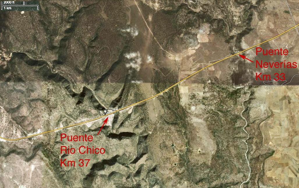
Puentes en los kilómetros 30-40
Puente Neverías en el kilómetro 33. Su calzada está a 107 metros de altura y soporta un vano central de 140 metros.
The Neverías Bridge deck is 107 meters high and supports a central span of 140 meters.Image by Eric Sakowski / HighestBridges.com
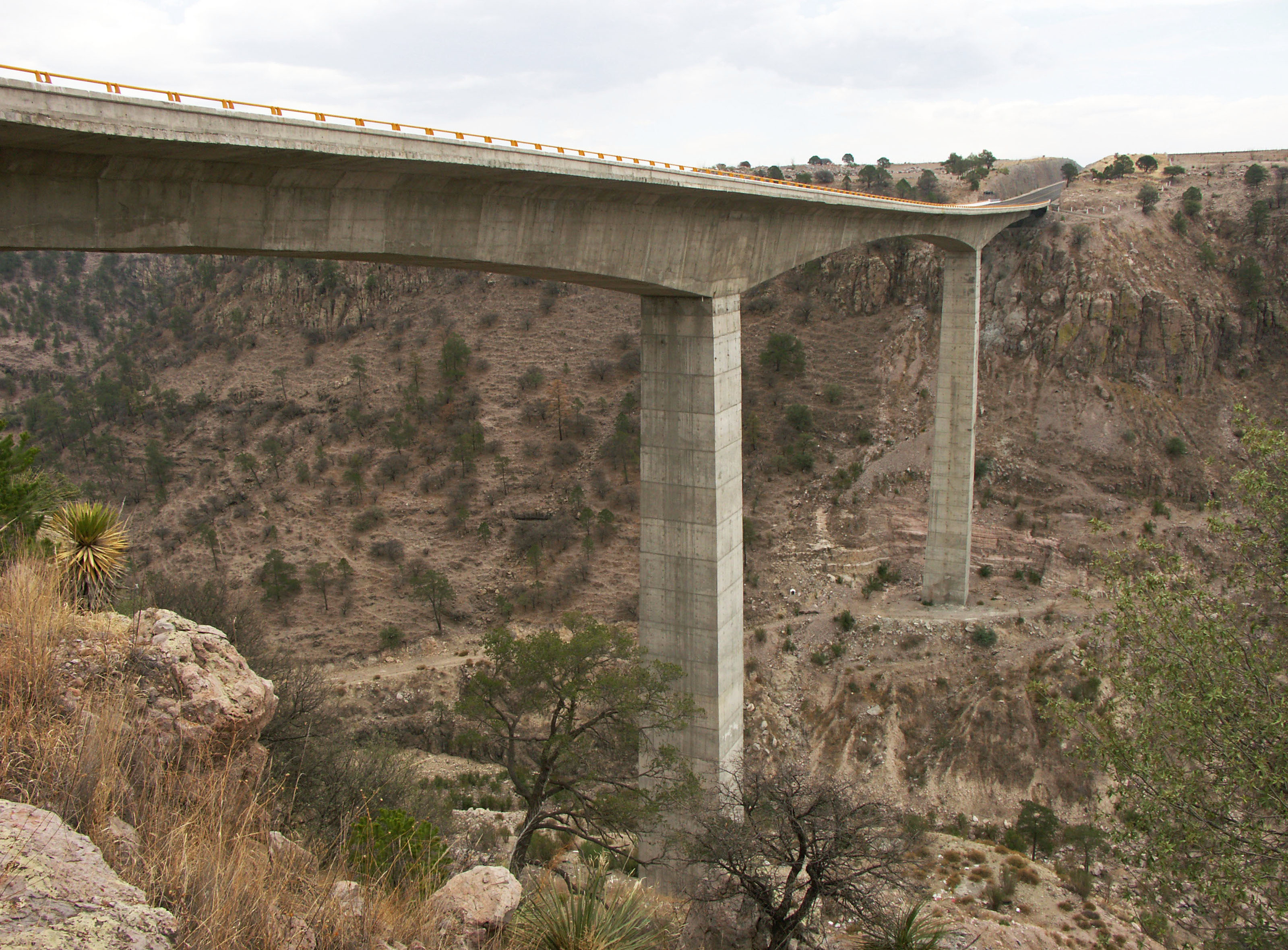
Puente Río Chico en el kilómetro 37. Su calzada está a 120 metros de altura y soporta un vano central de 140 metros.
The Rio Chico Bridge deck is 120 meters high and supports a central span of 140 meters. Image courtesy of Héctor S. Ovalle Mendivil / Coconal
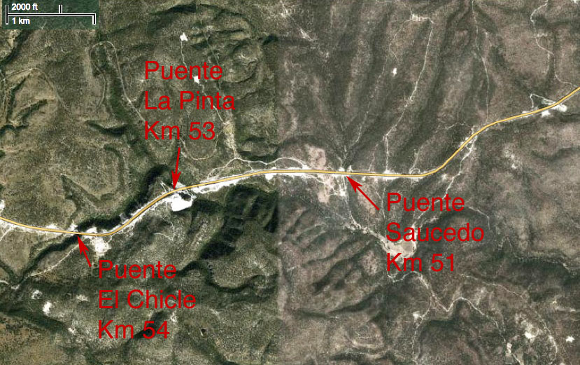
Puentes en los kilómetros 50-55
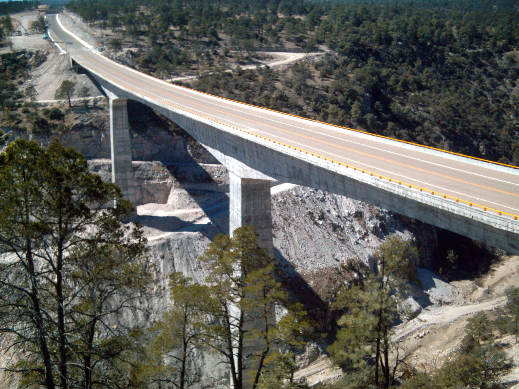
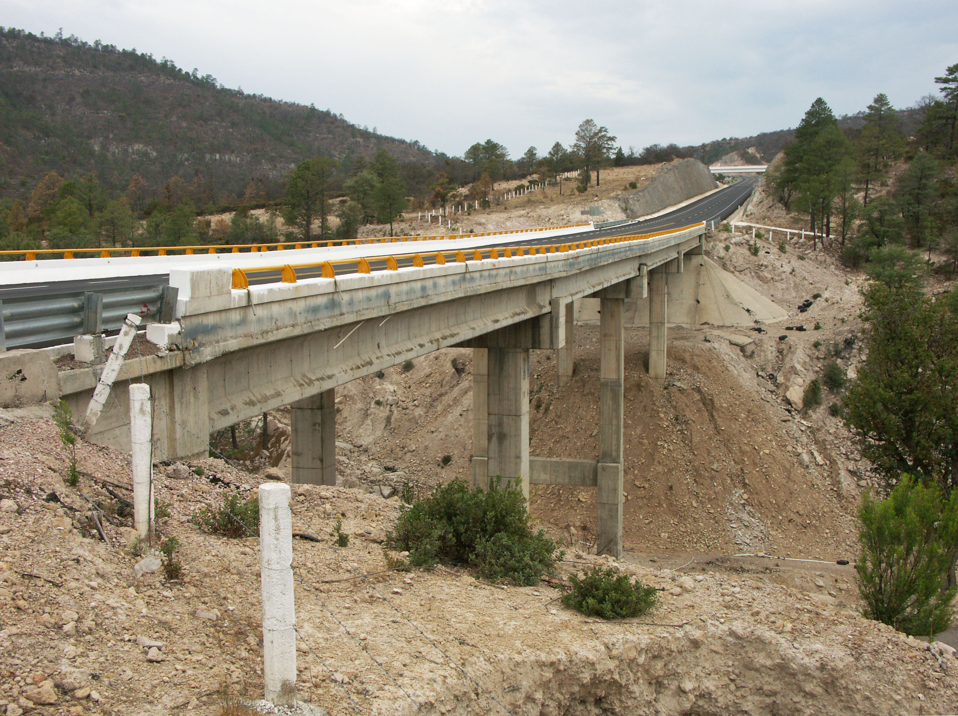
Puente Saucedo en el kilómetro 51. Image by Eric Sakowski / HighestBridges.com
Puente La Pinta en el kilómetro 53. El puente tiene a 70 metros de altura.
The Pinta Bridge is 70 meters high. Image by Eric Sakowski / HighestBridges.com
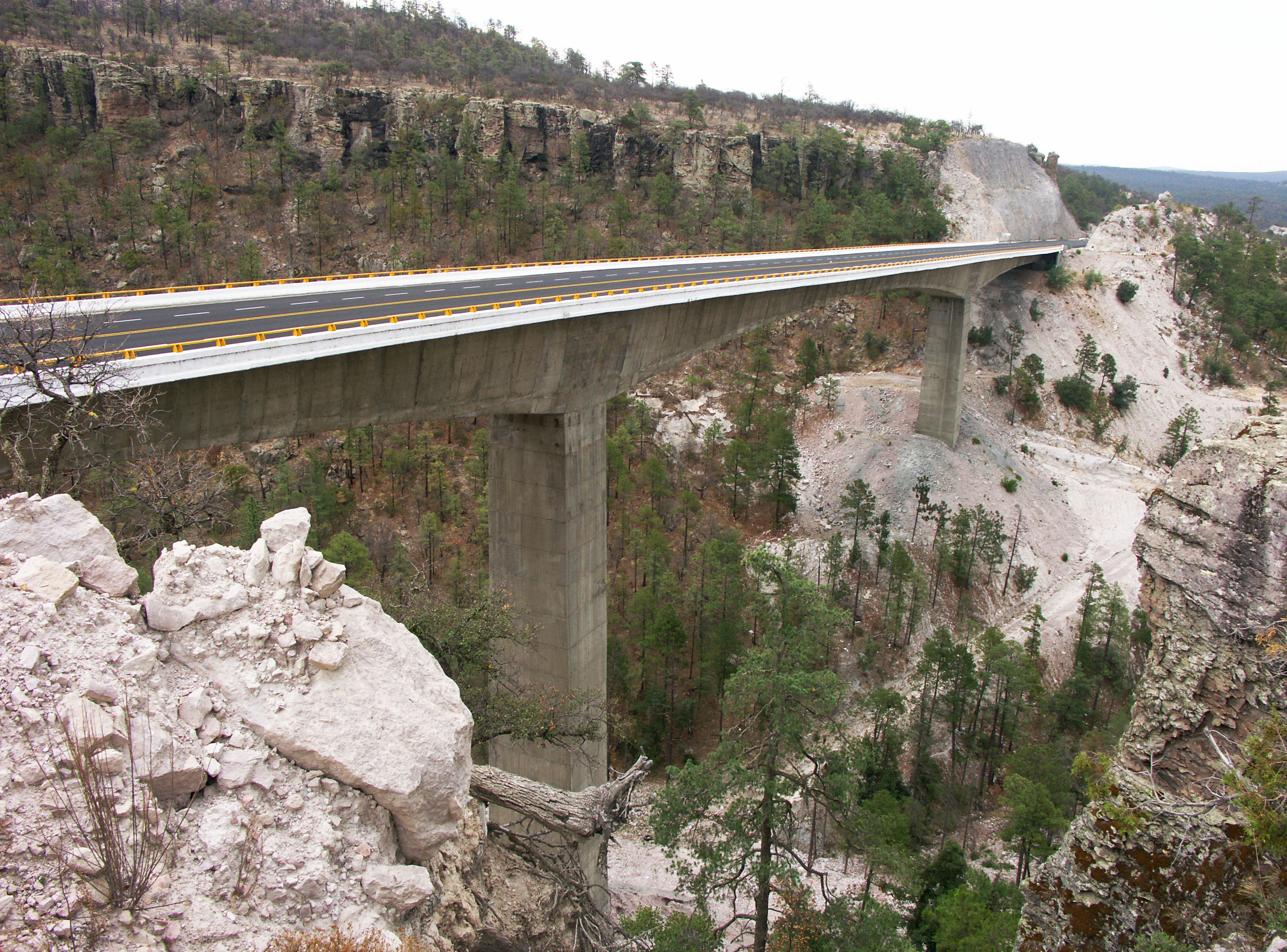
Puente El Chicle en el kilómetro 54. Image by Eric Sakowski / HighestBridges.com
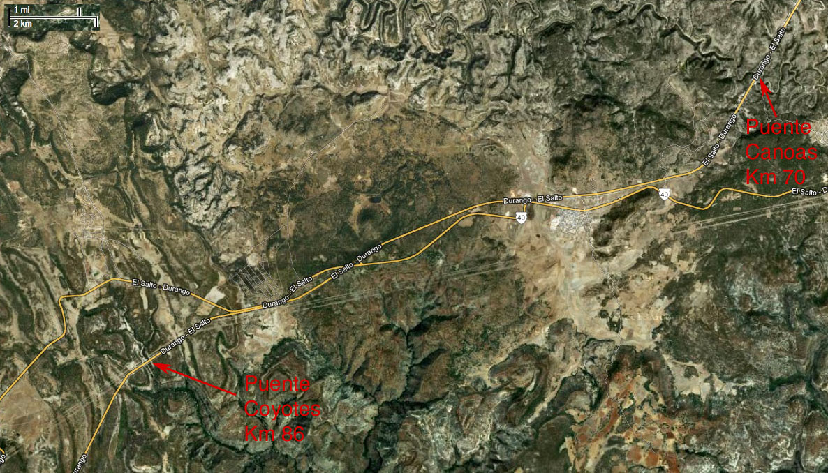
Puentes en los kilómetros 68-88
Puente Río Canoas en el kilómetro 70. Image by Eric Sakowski / HighestBridges.com
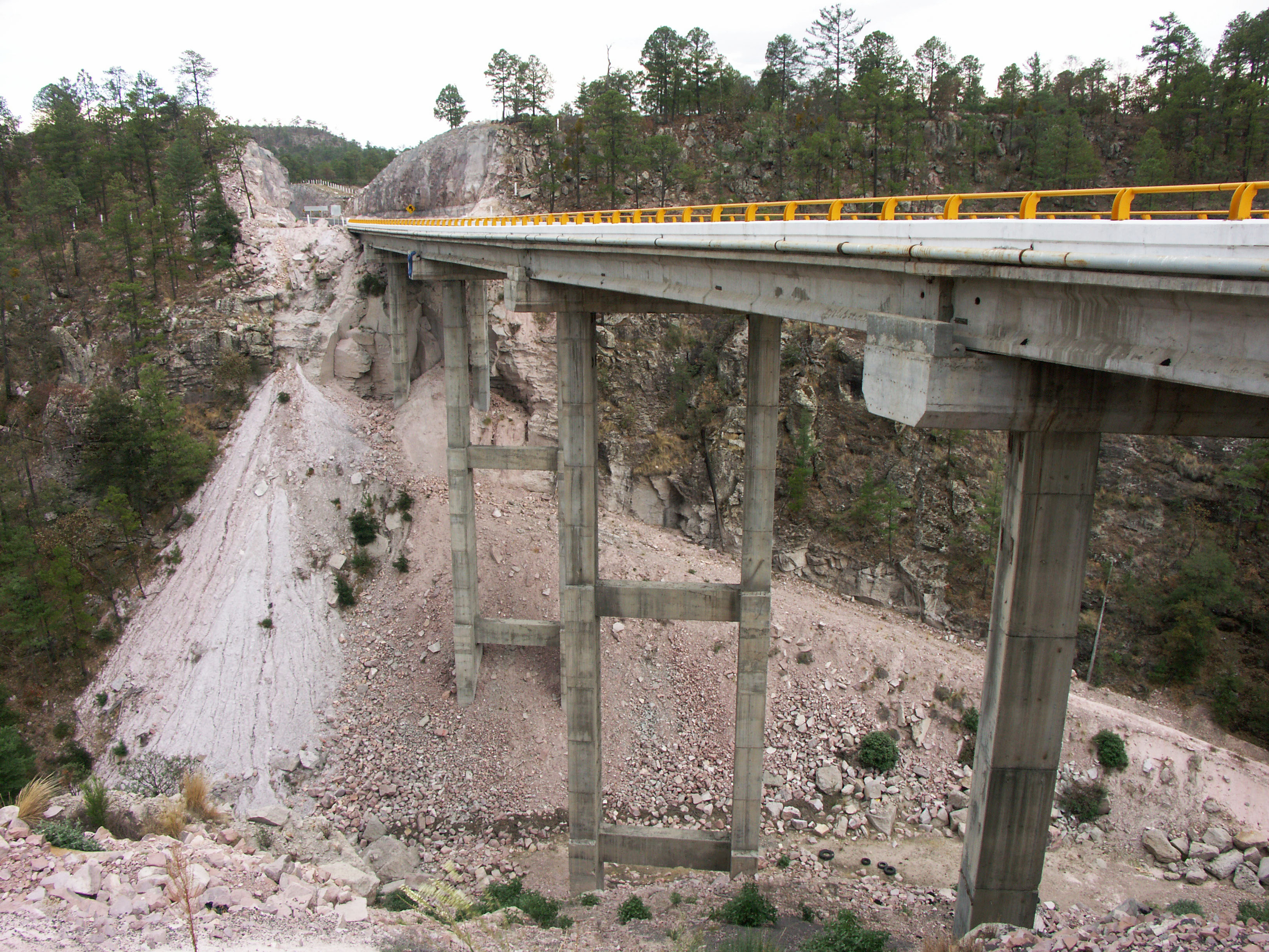
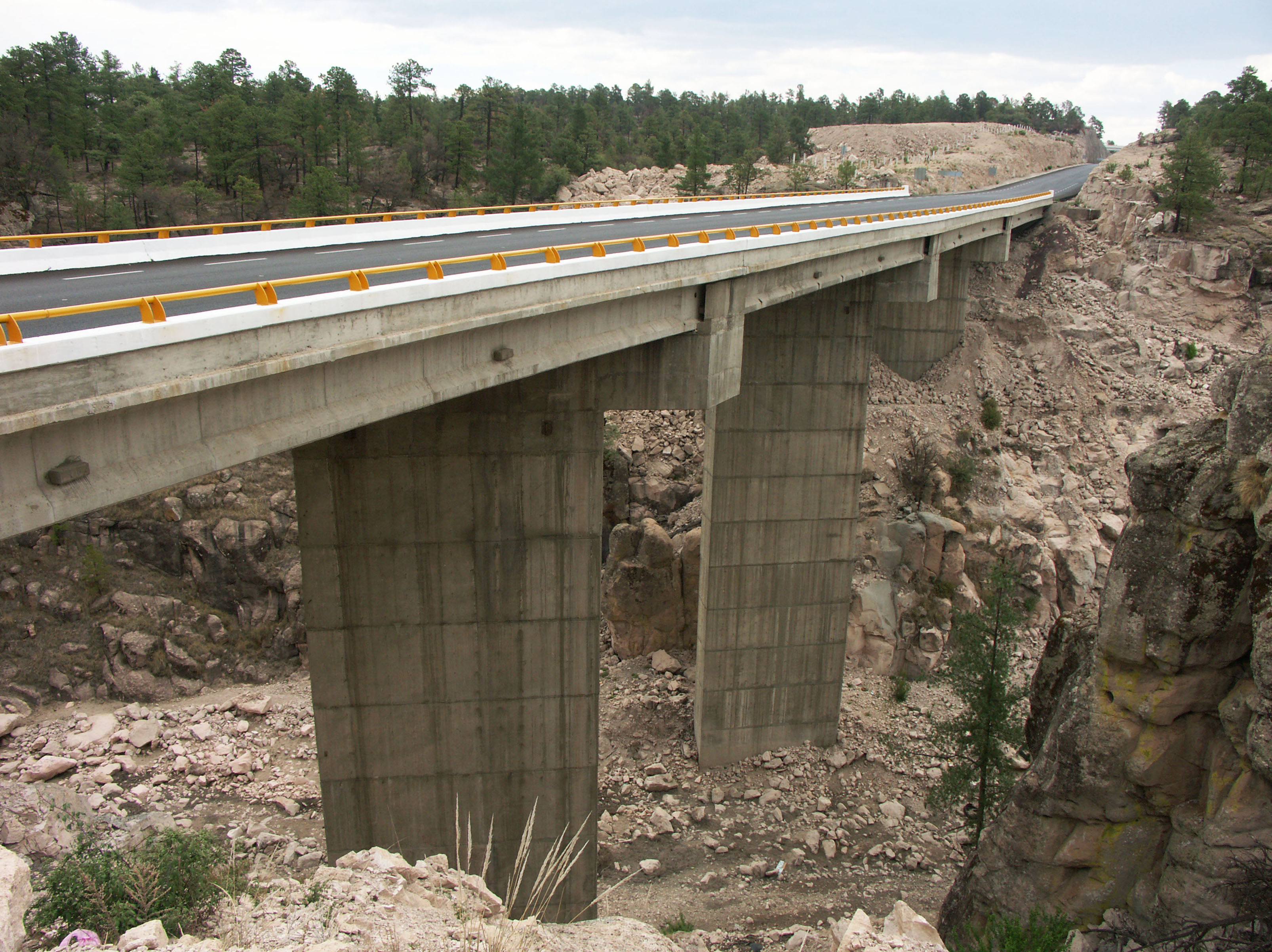
Puente Coyotes en el kilómetro 86. Image by SCT
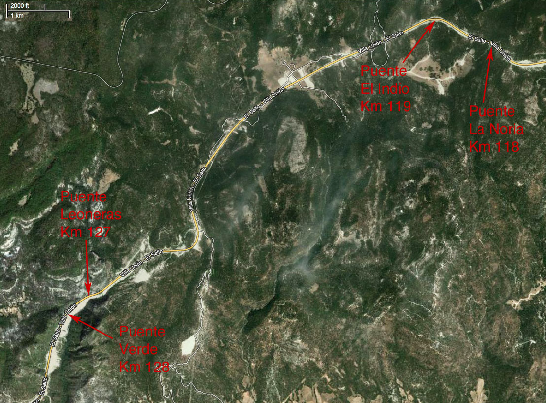
Puentes en los kilómetros 117-130
Puentes La Noria y El Indio en el kilómetro 119. Image by SCT
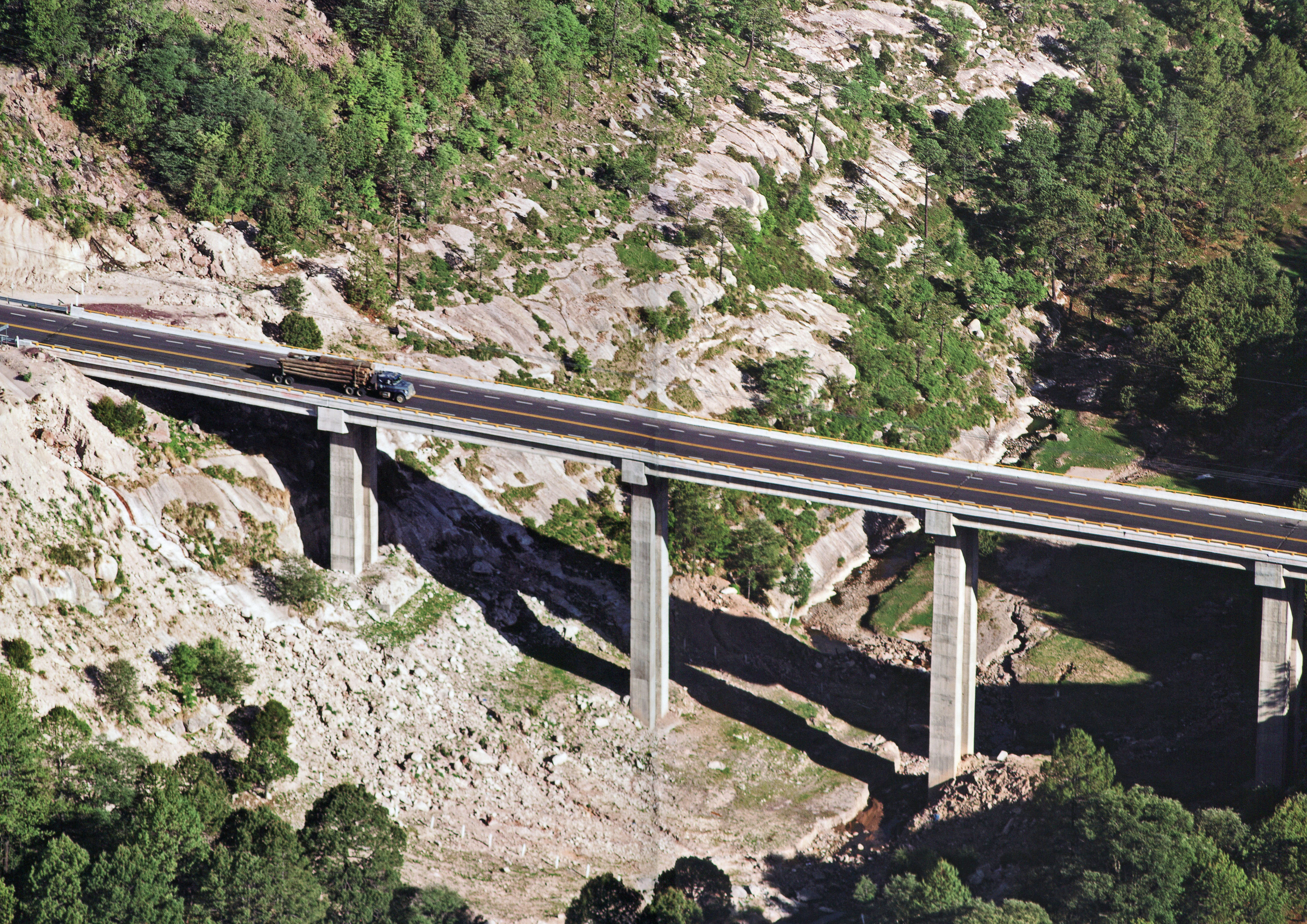
Puente El Indio. El puente cuenta con 8 claros: uno de 30, 6 de 40 y uno de 30 metros. Image by SCT
Puente El Indio. Image by Eric Sakowski / HighestBridges.com
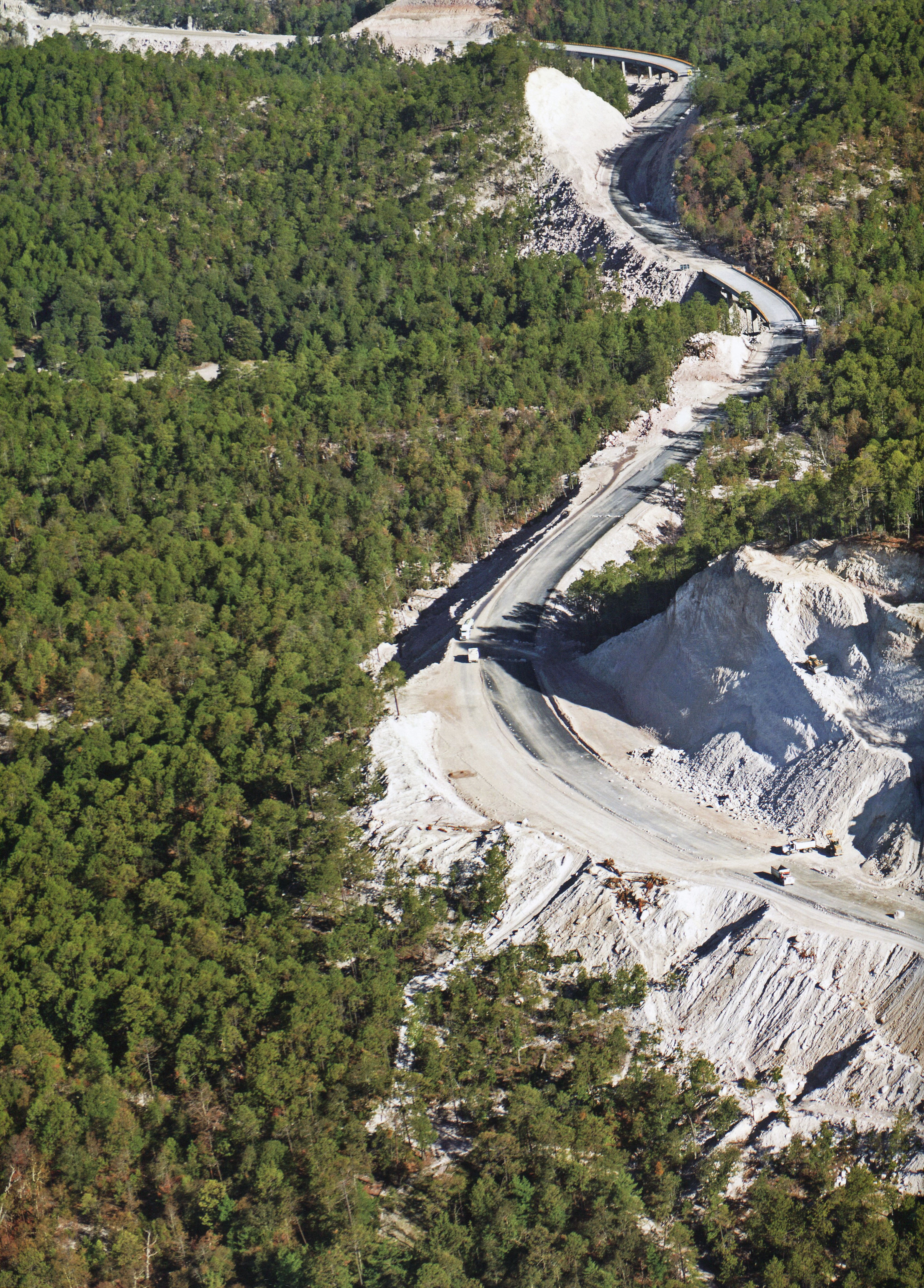
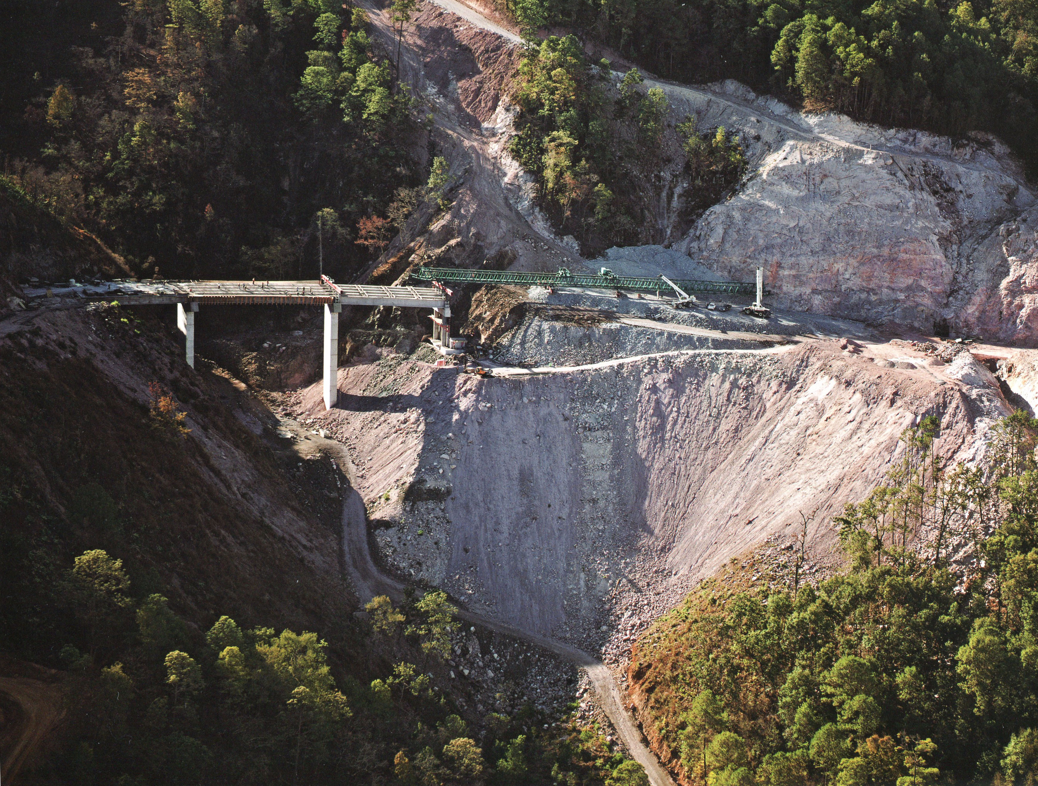
Principios de la construcción de la carretera a la altura del kilómetro 127.
Early construction of highway at kilometer 127. Image by SCT
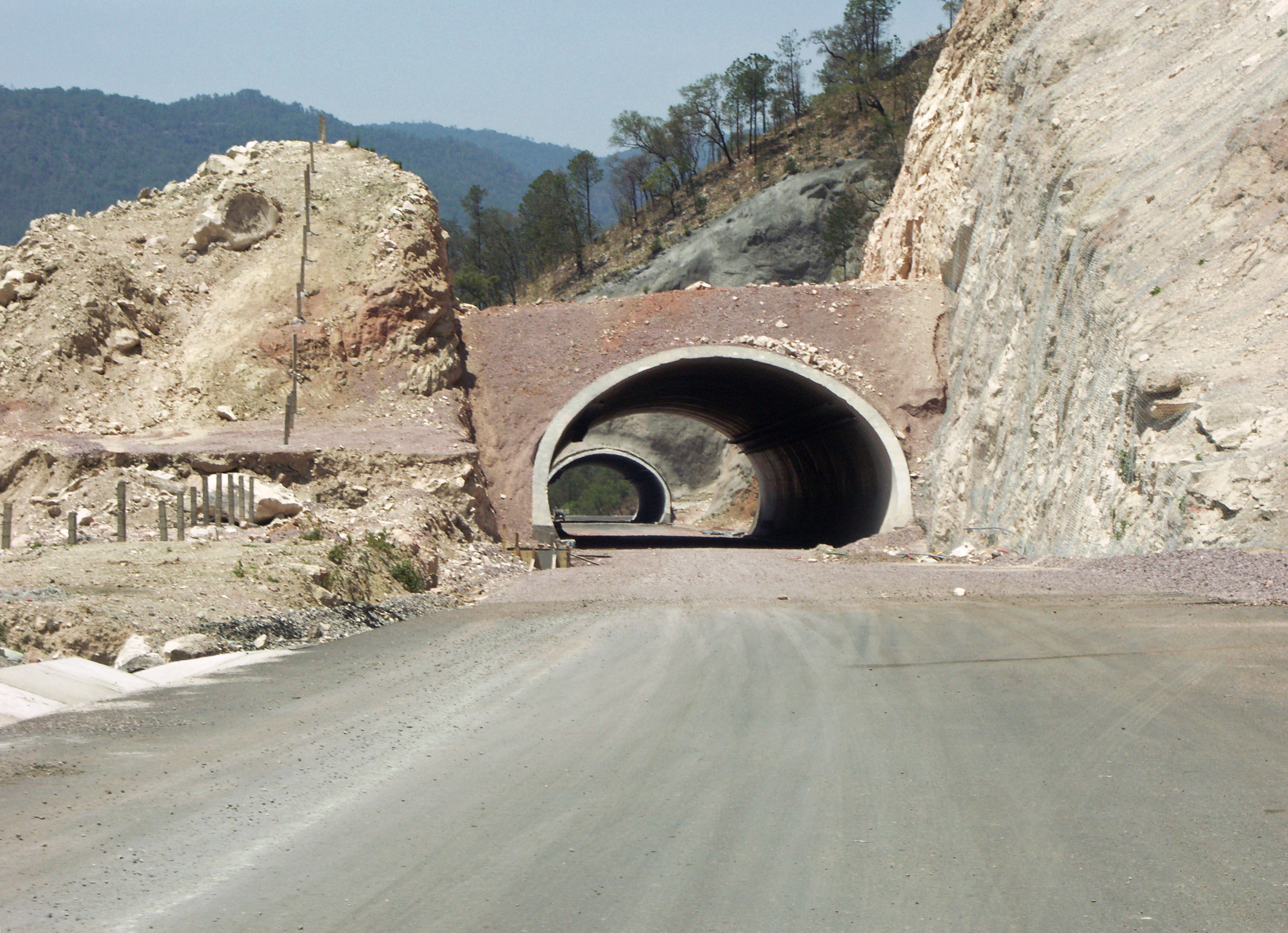
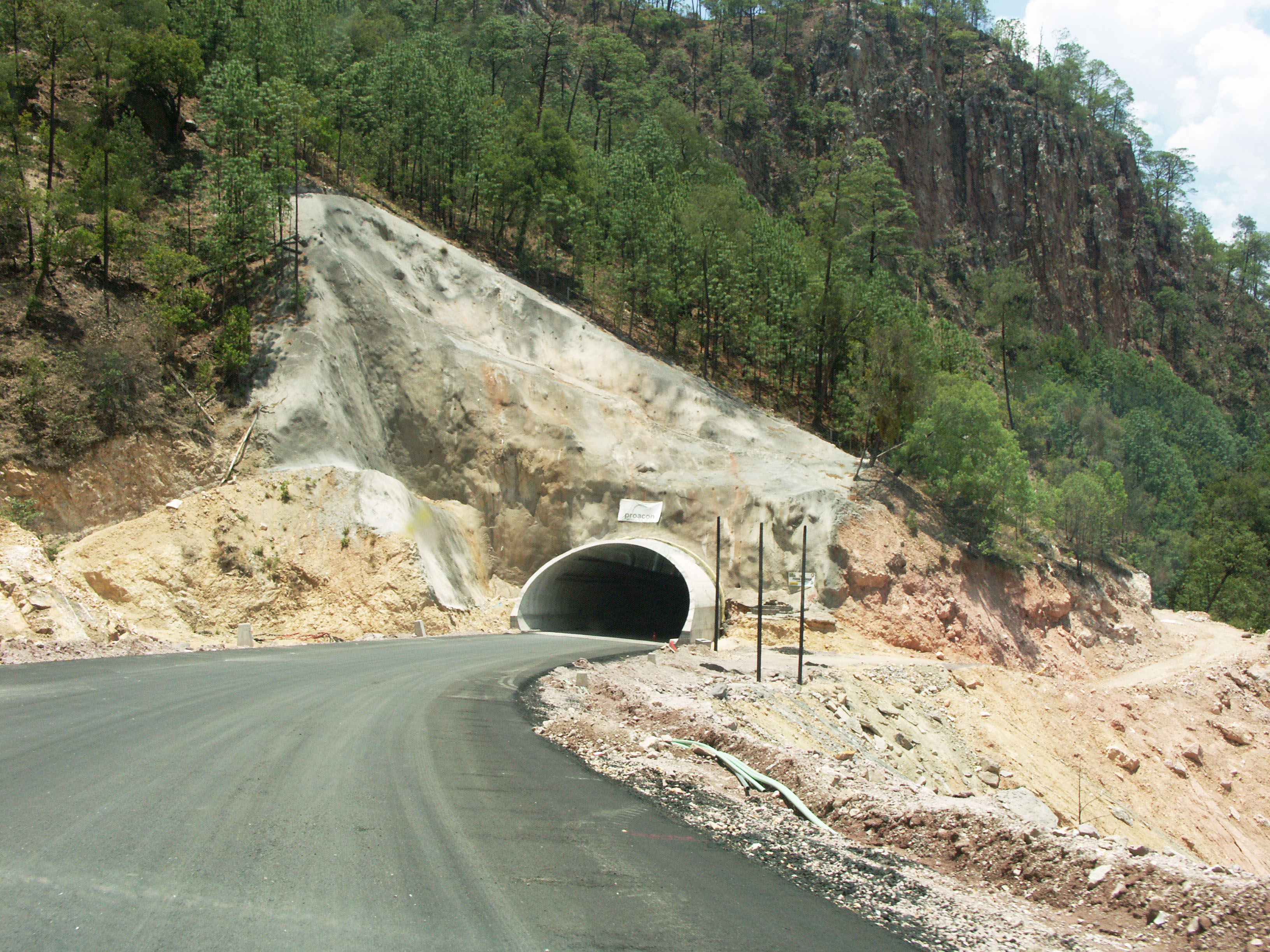
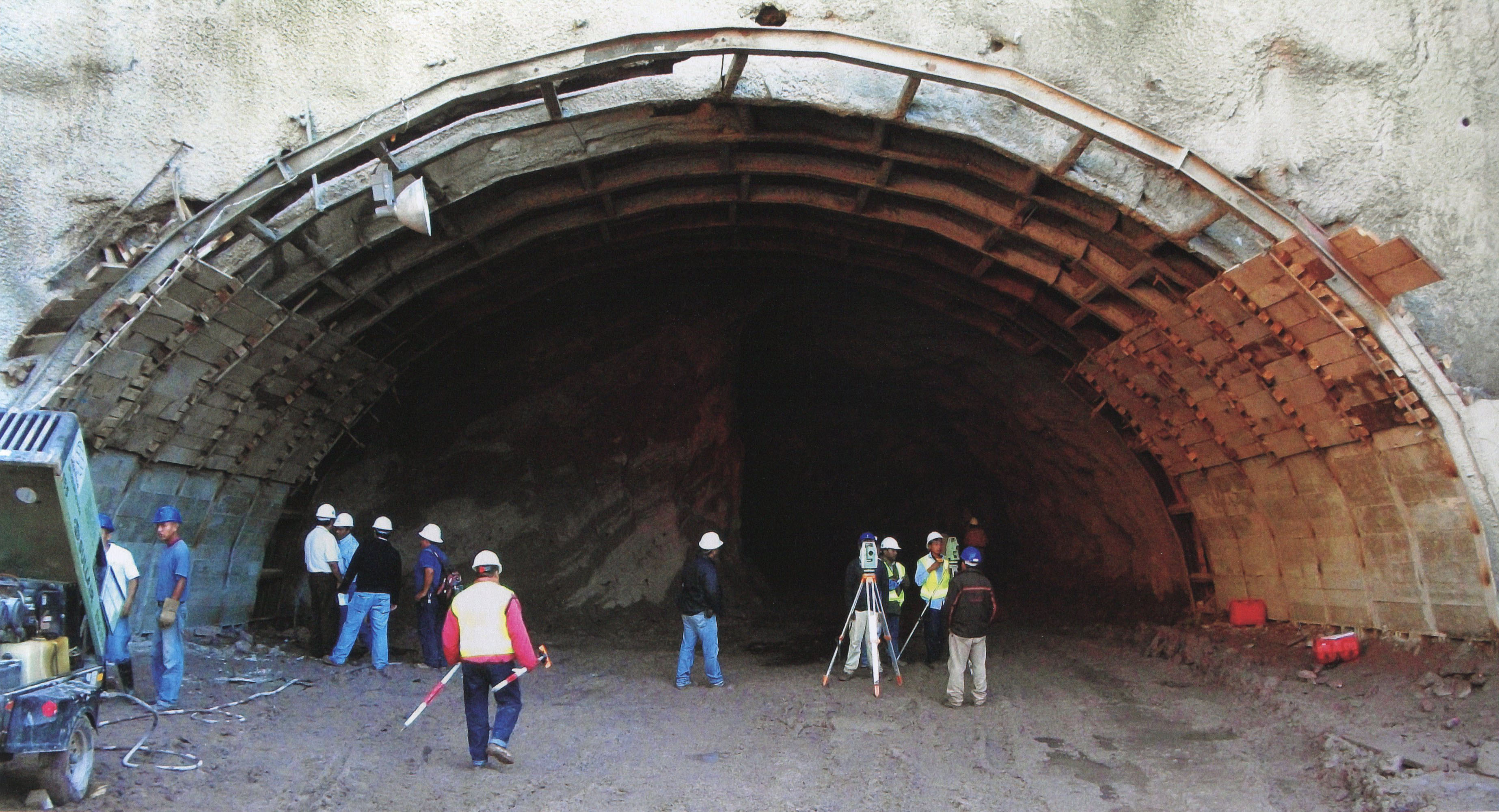
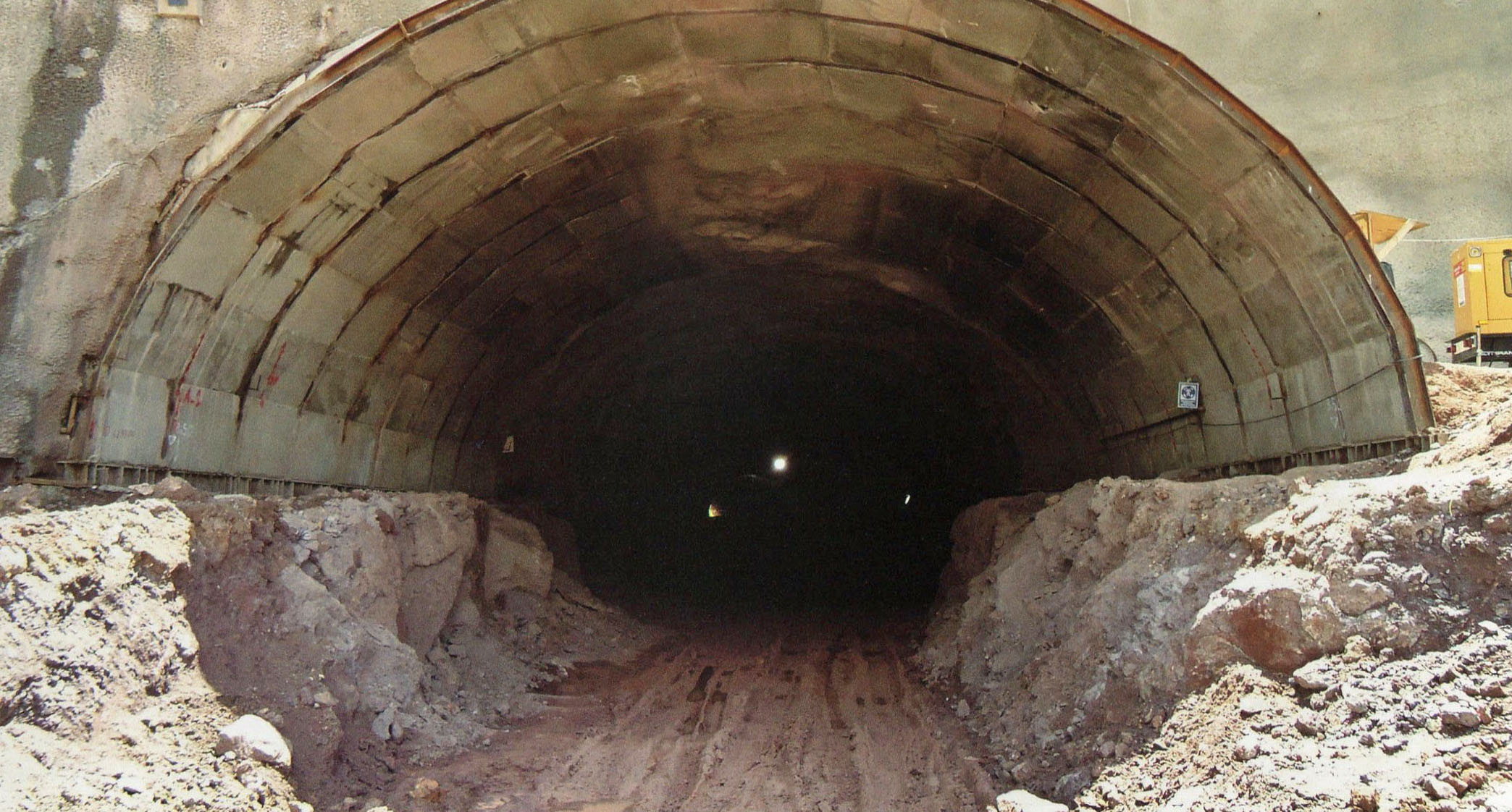
Túnel Leonera I y II en el kilómetro 127.
Túneles Leonera I y II en el kilómetro 127. Con 18,000 metros de túnel, ¡la nueva carretera Durango-Mazatlán tendrá más kilómetros de túneles carreteros que los que se han construido en toda la historia de México!
With 18,000 meters of tunnel, the new Durango-Mazatlan highway will have more kilometers of road tunnel then have been built in the entire course of Mexico's history! Image by SCT
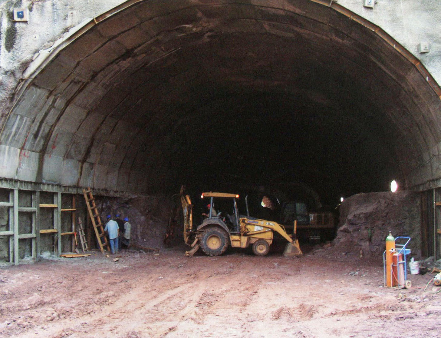
Túnel Leonera I. Image by Eric Sakowski / HighestBridges.com
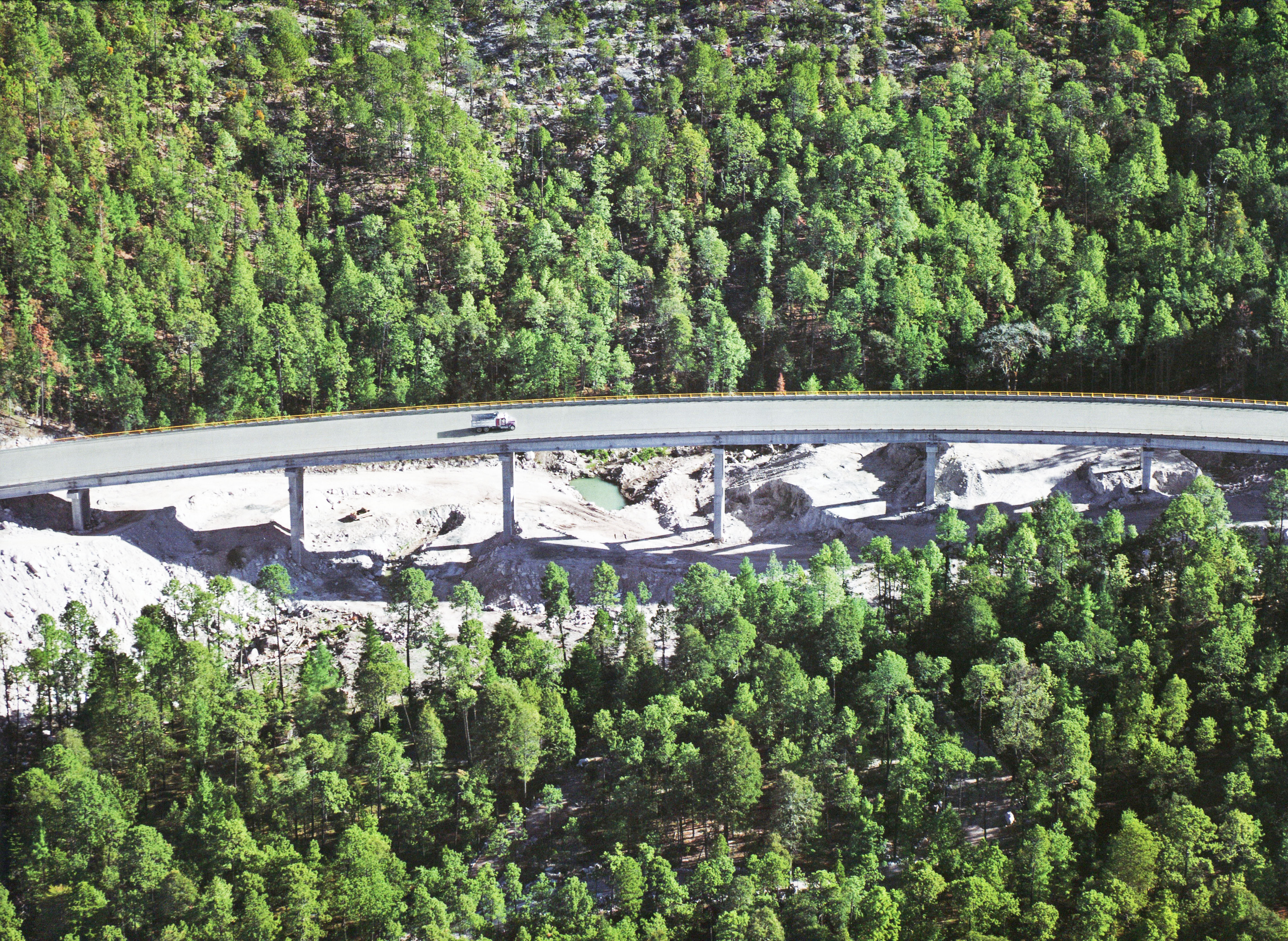
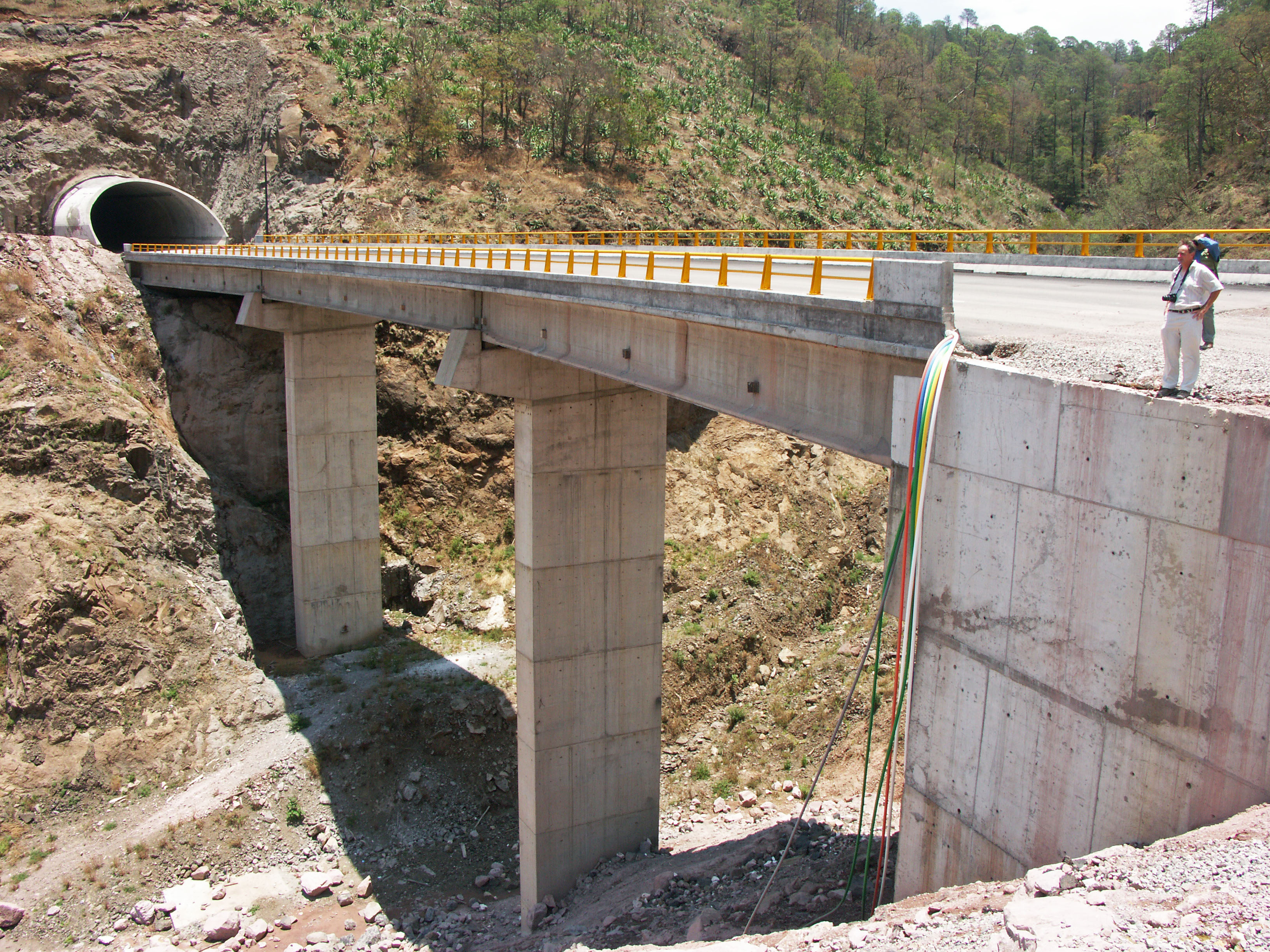
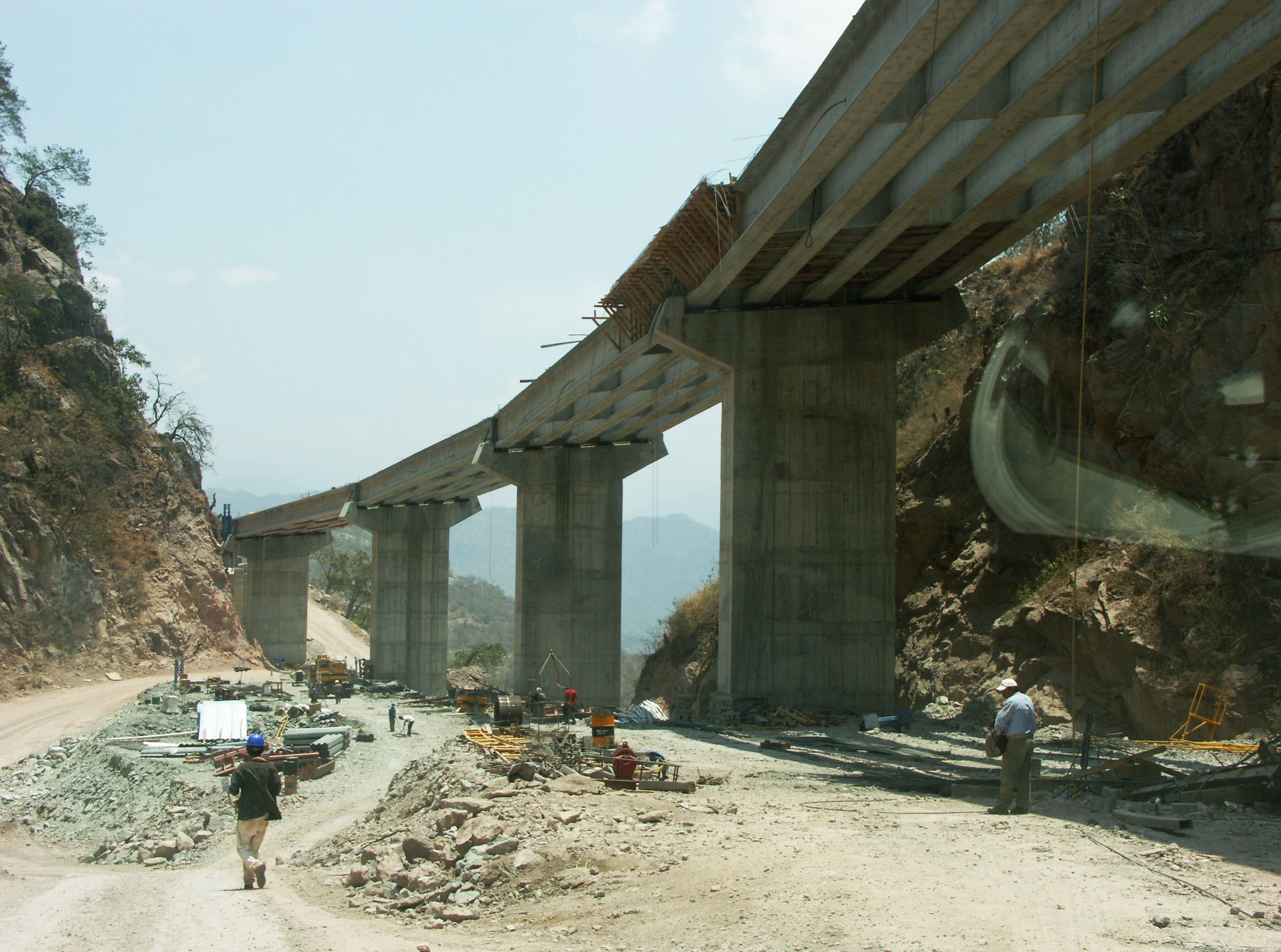
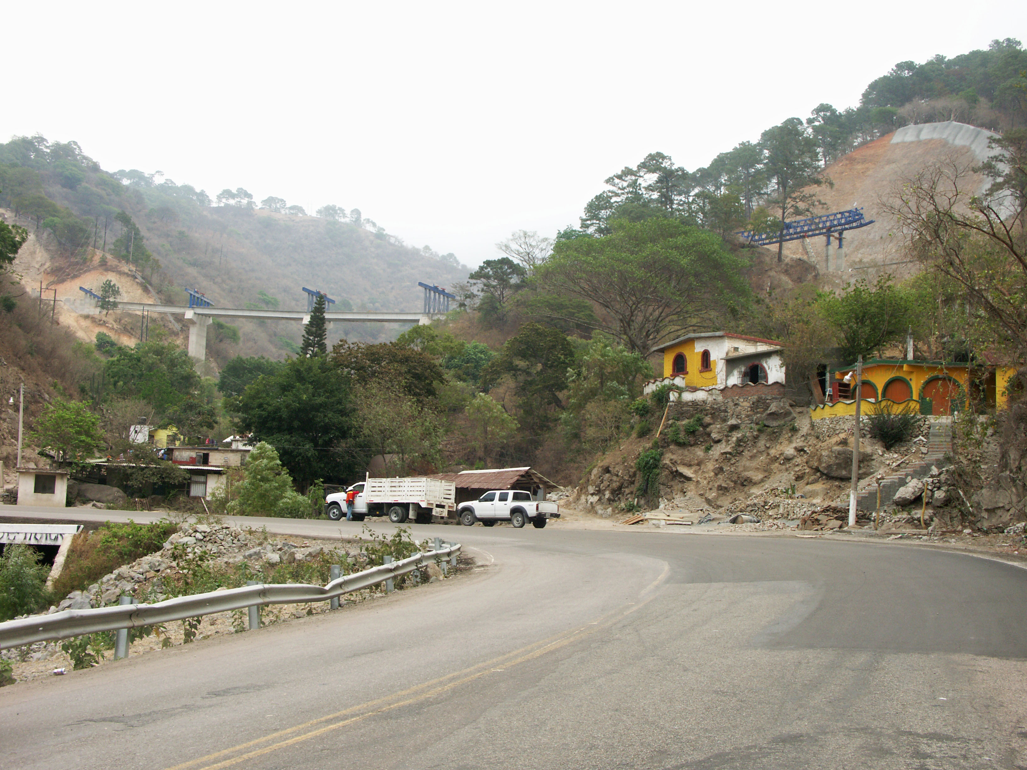
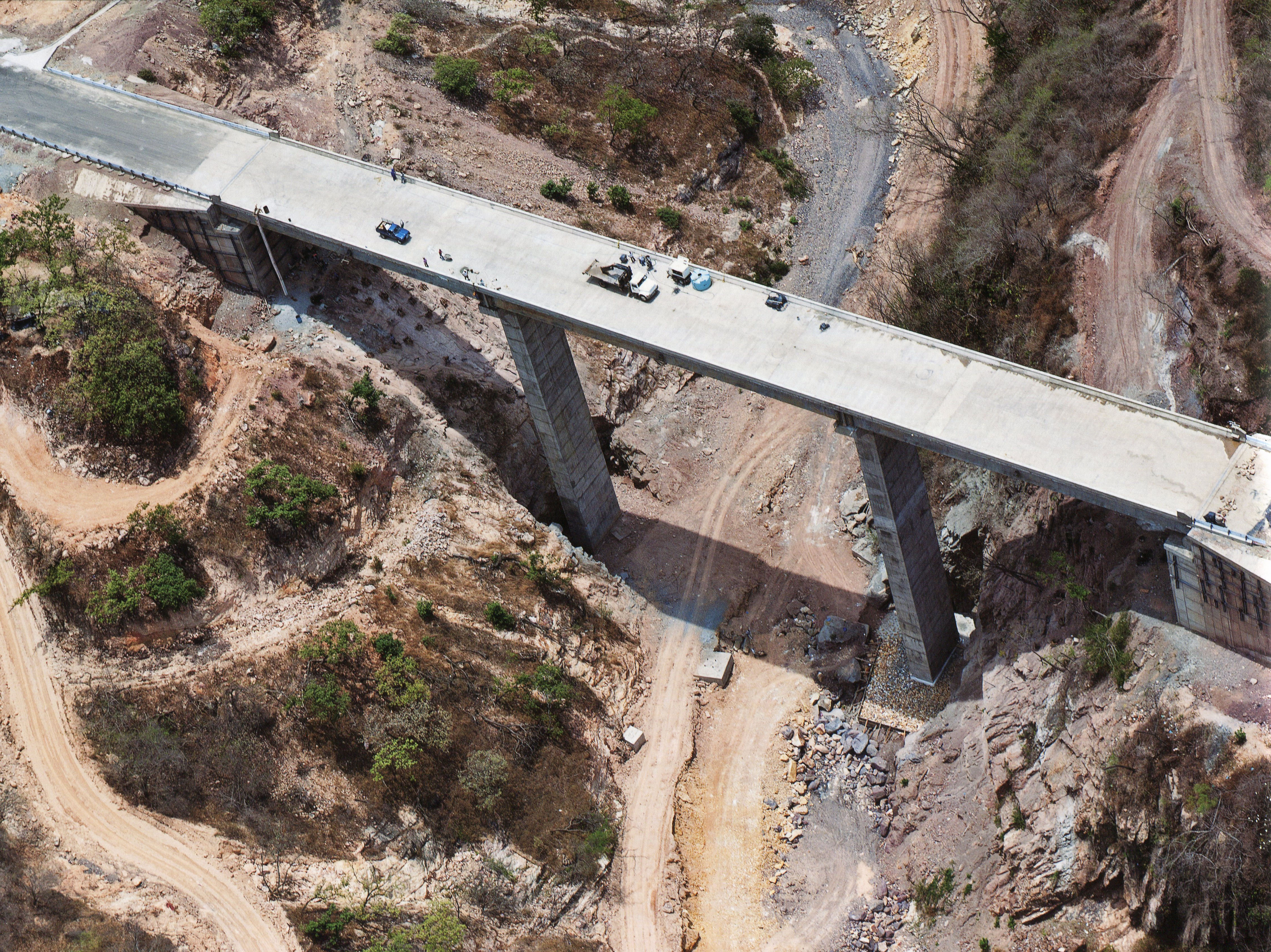
Puente Leoneras. El puente cuenta con 4 claros: uno de 31.5, 2 de 42 y uno de 31.5 metros. En el primer plano, la carretera se apoya en un relleno de grava detenido por un muro de concreto.
In the foreground the road will be supported on a gravel fill retained by a concrete wall. Image by Eric Sakowski / HighestBridges.com
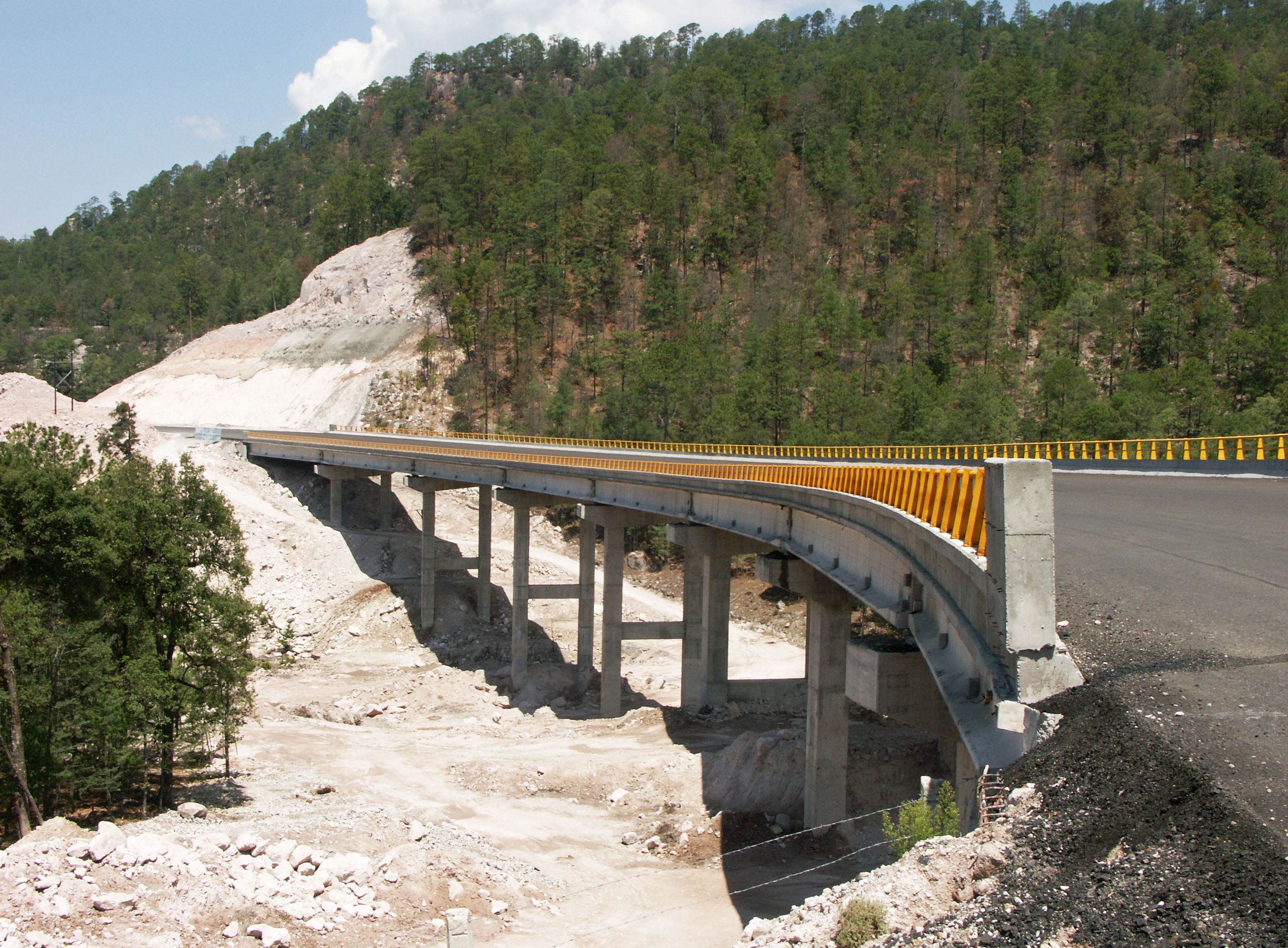
Puente Verde en el kilómetro 128. El puente cuenta con 3 claros de 42 metros. Image by Eric Sakowski / HighestBridges.com
Túneles Los Alacranes y Chavaria Nuevo III en el kilómetro 129. Image by Eric Sakowski / HighestBridges.com
Puentes en los kilómetros 130-140
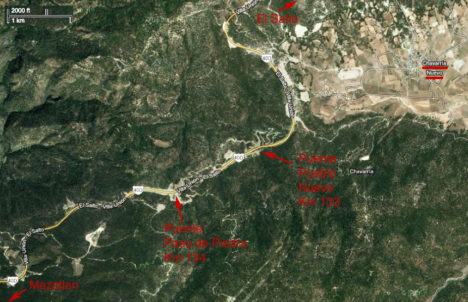
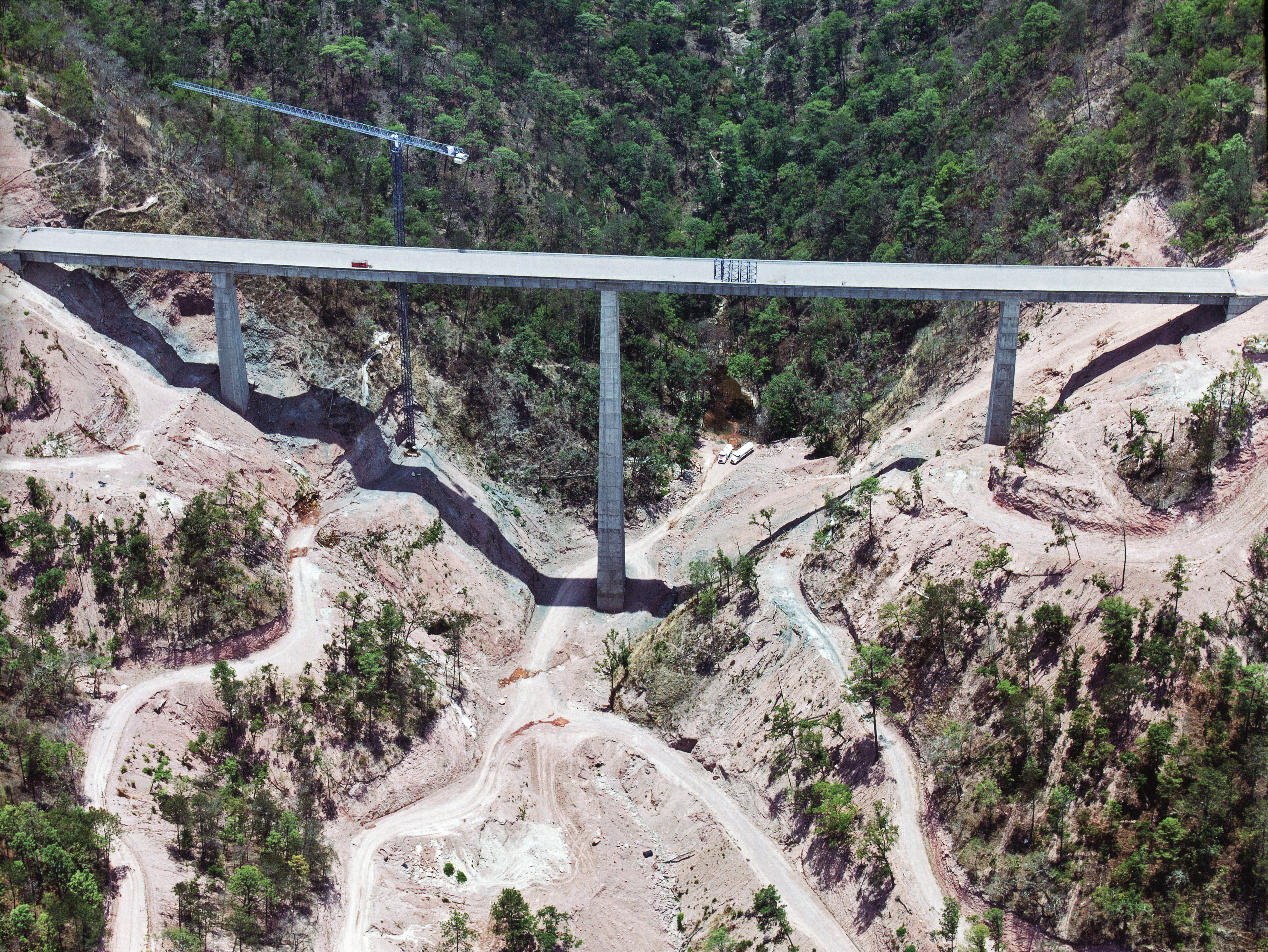
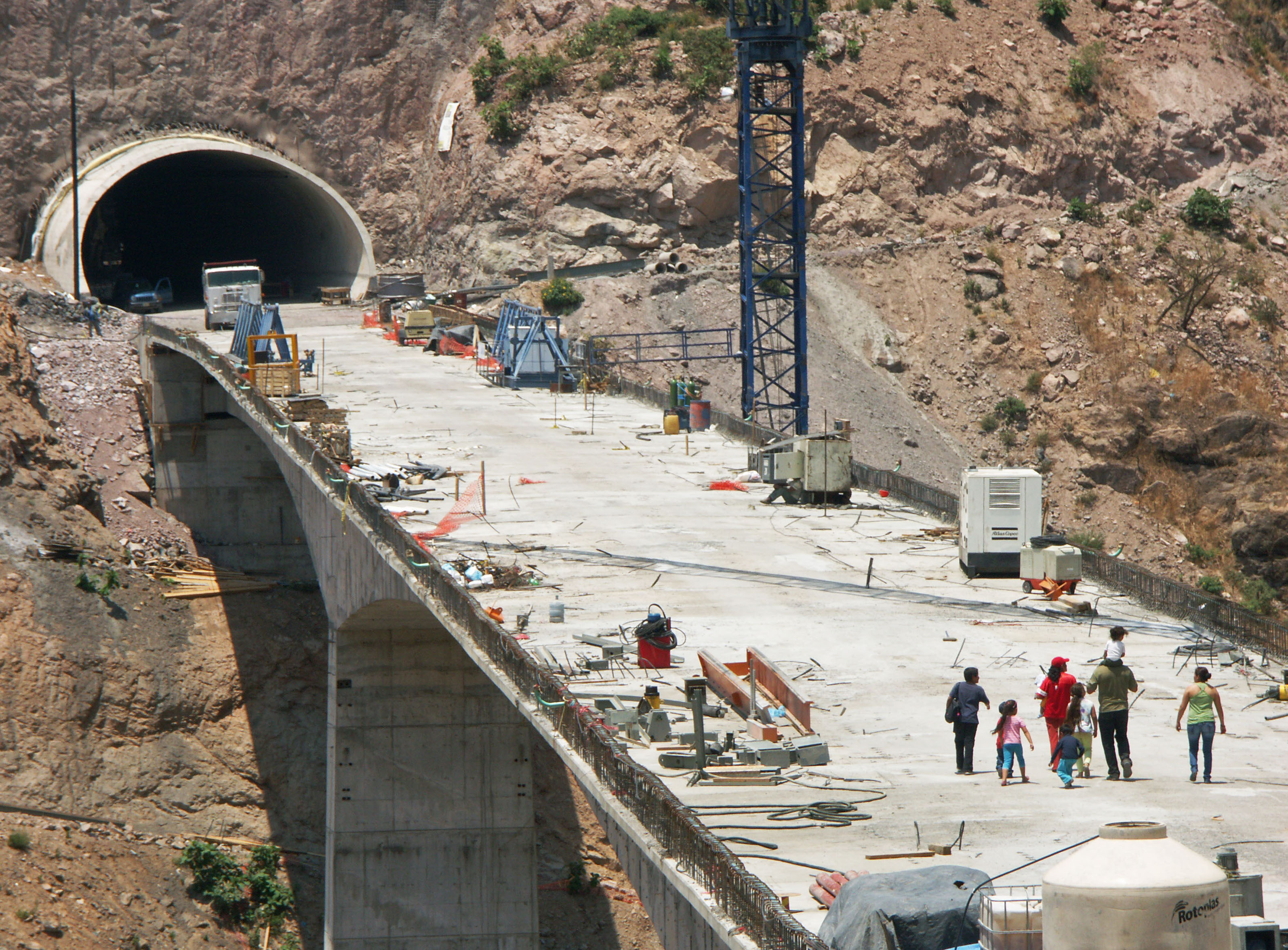
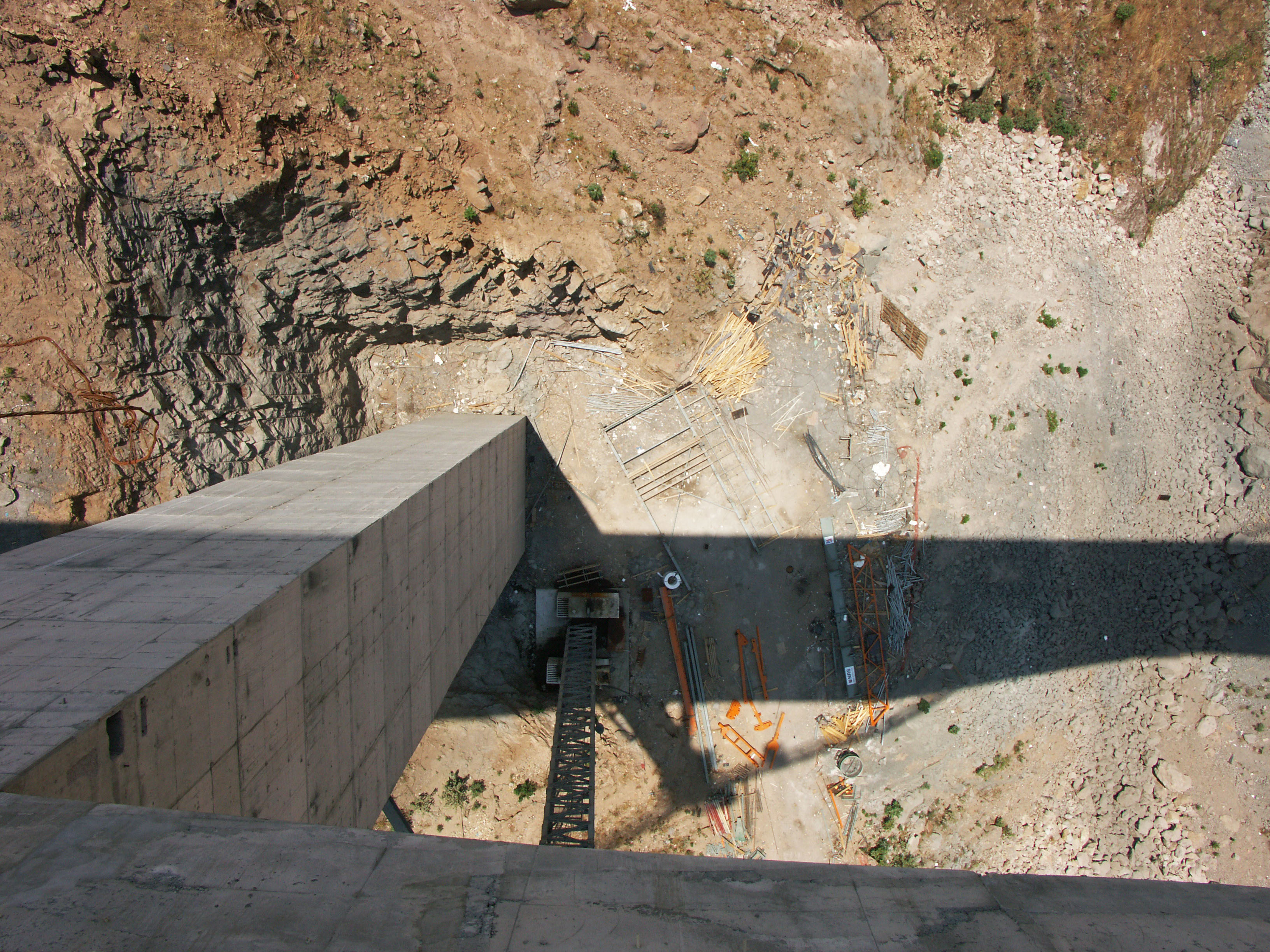
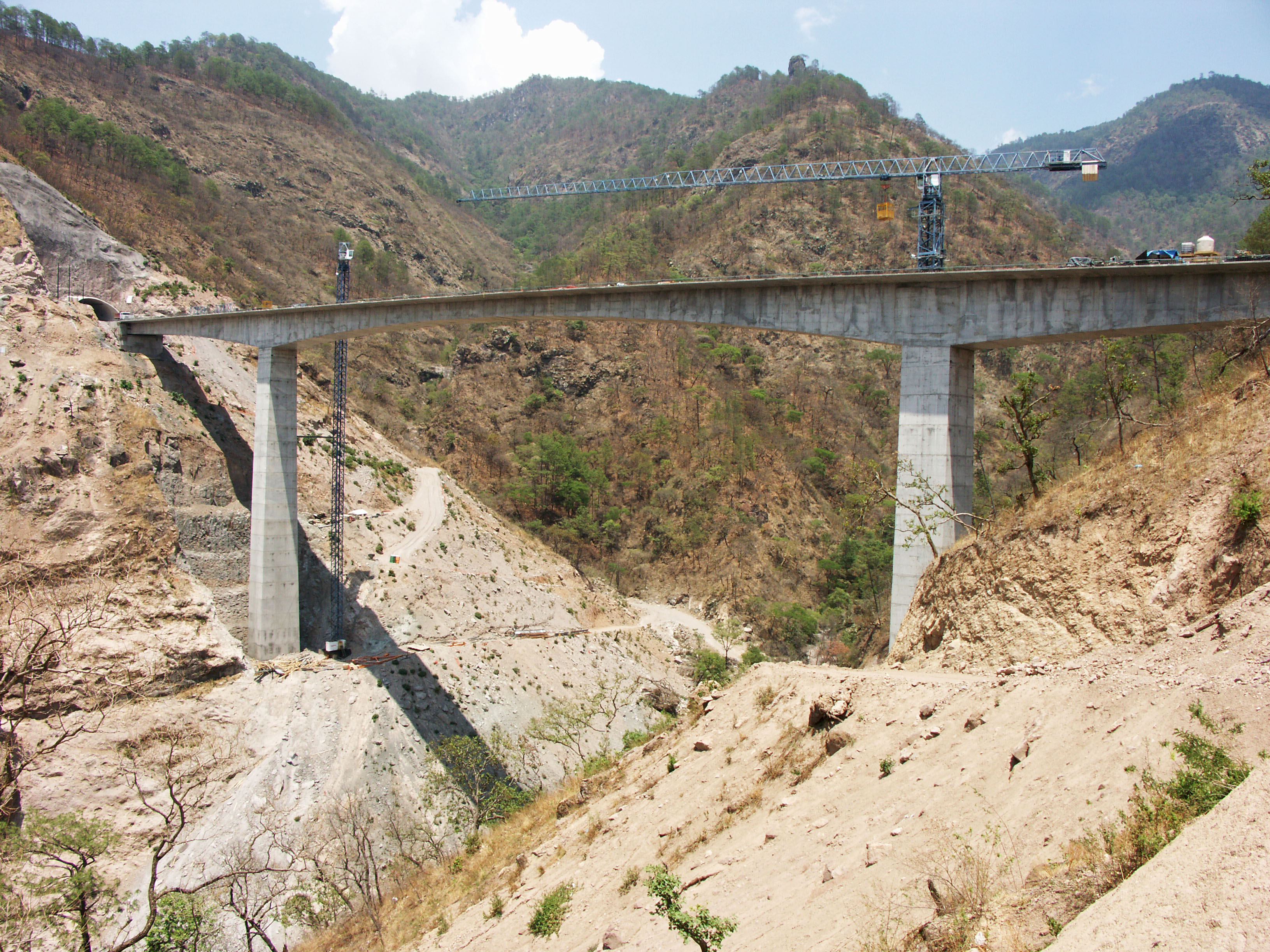
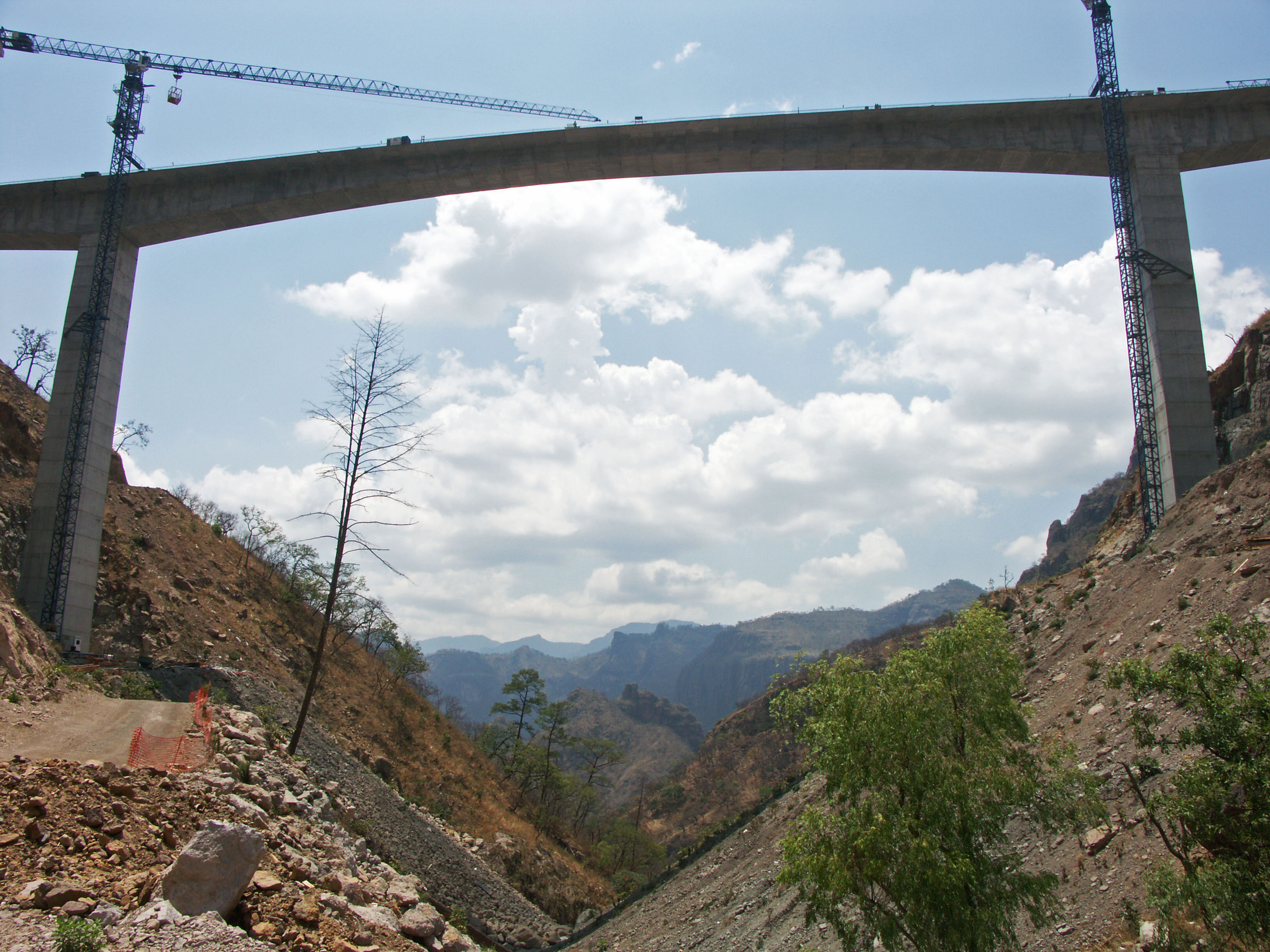
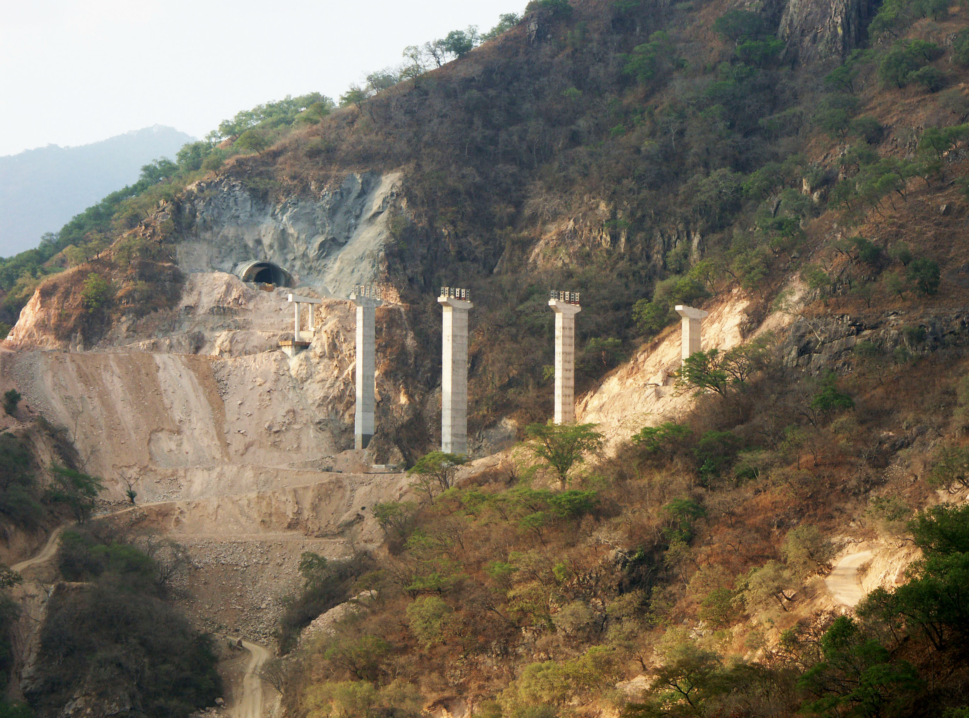
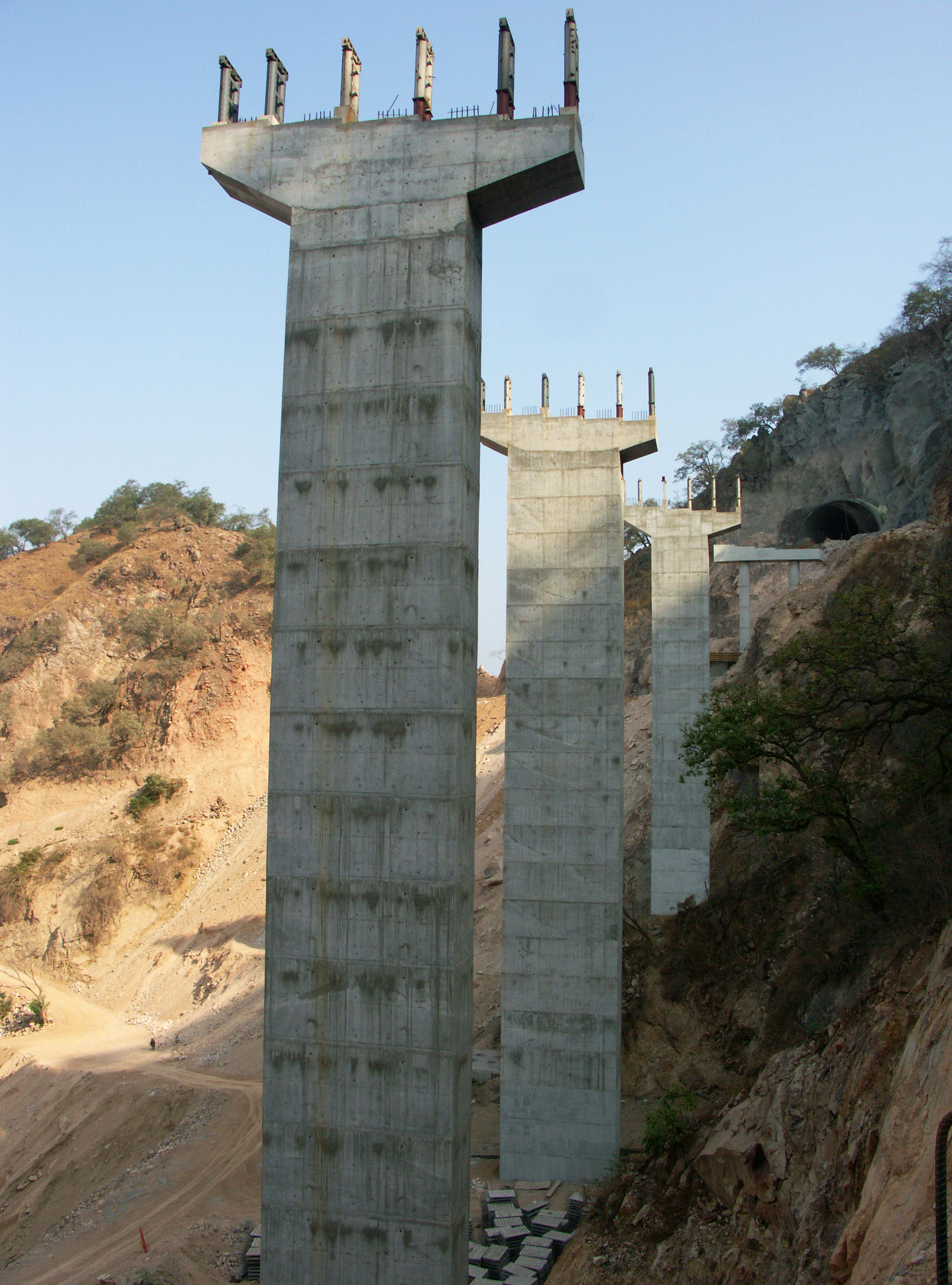
Puente Pueblo Nuevo en el kilómetro 133. El puente cuenta con 4 claros: uno de 55, 2 de 106 y uno de 55 metros. Su altura es de 114 metros.
The height is 114 meters. Image by SCT
Puente Pueblo Nuevo. Image by Eric Sakowski / HighestBridges.com
Puente Pueblo Nuevo. Image by Eric Sakowski / HighestBridges.com
Puente Pueblo Nuevo. Image by SCT
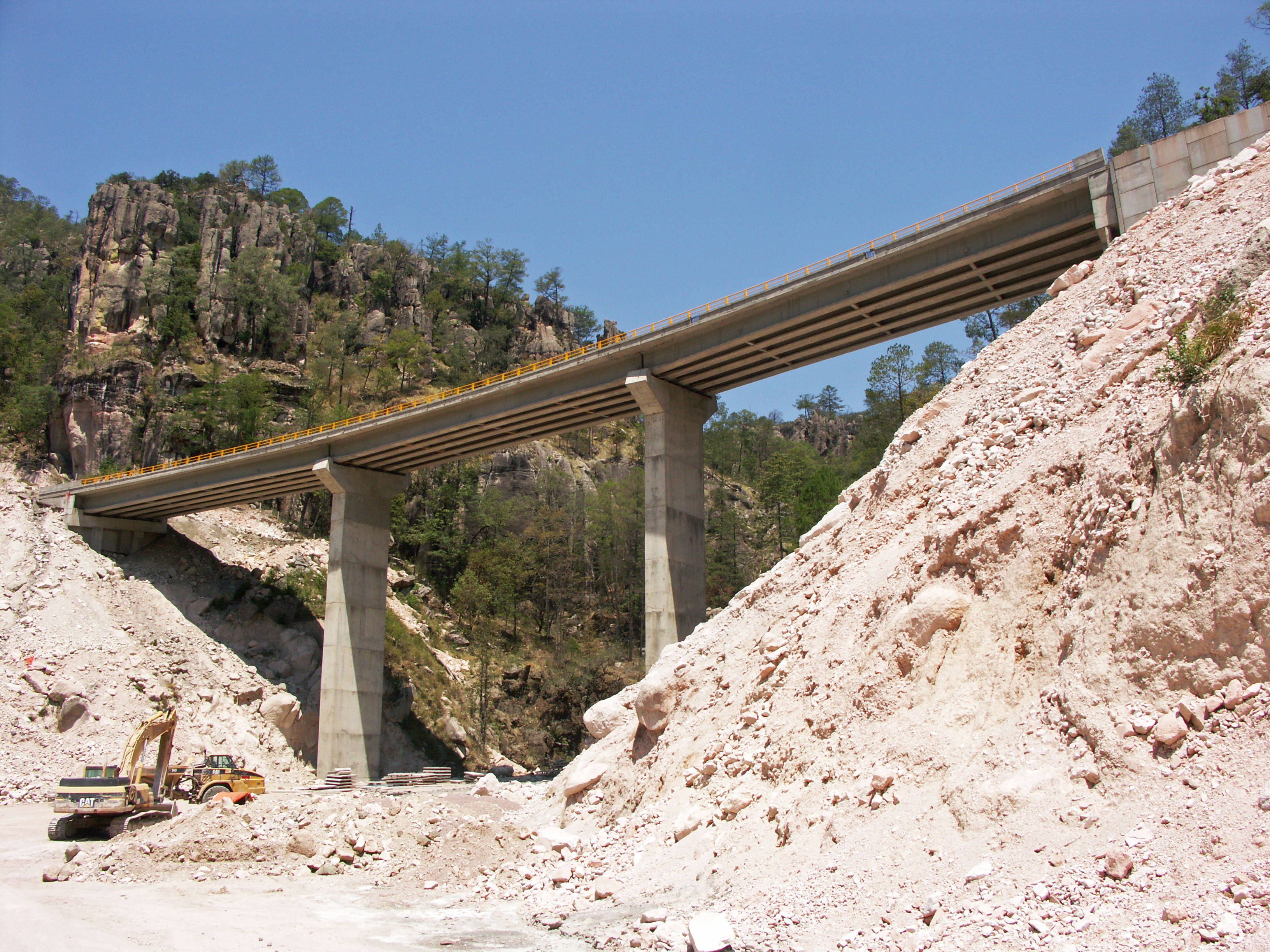
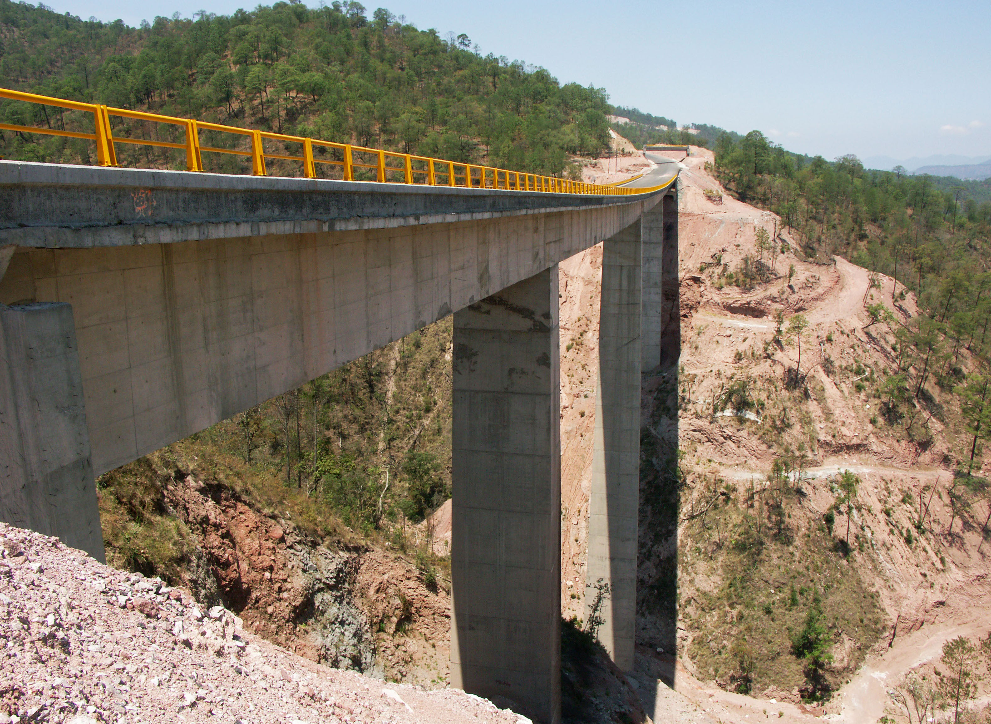
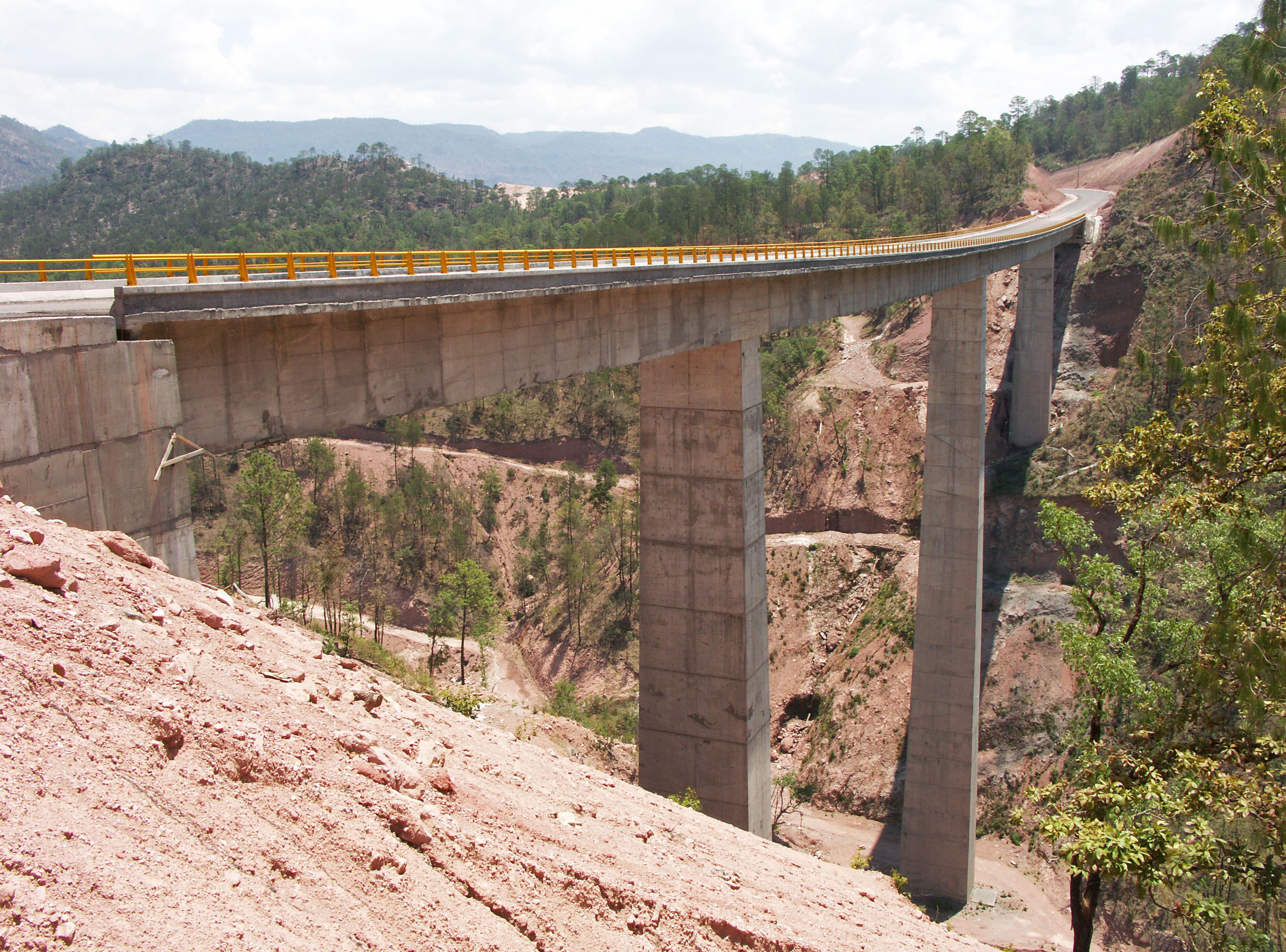
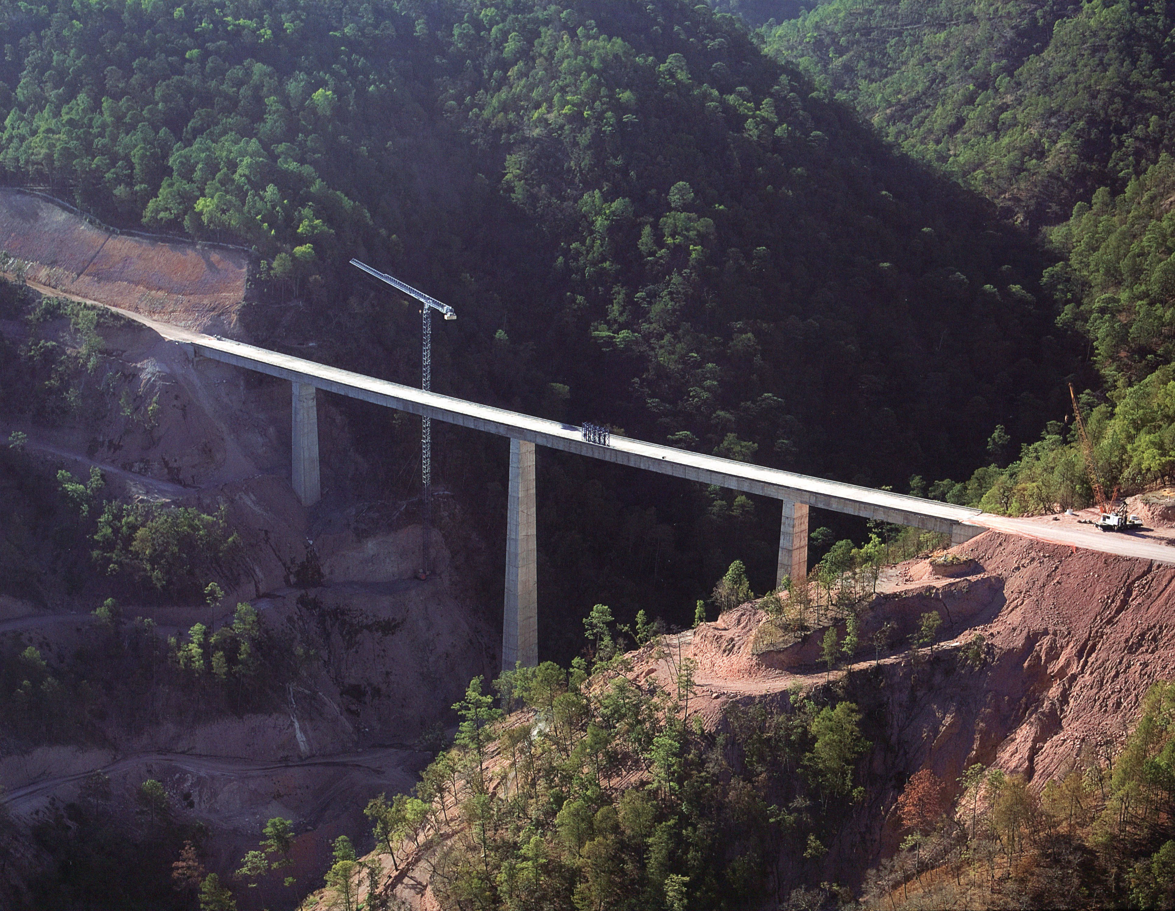
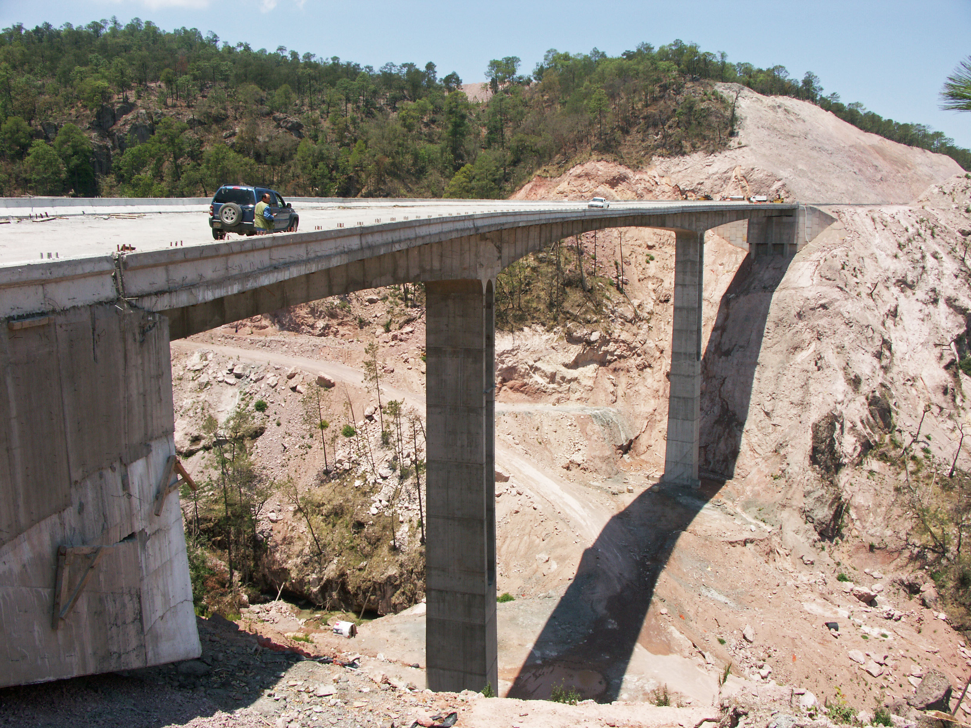
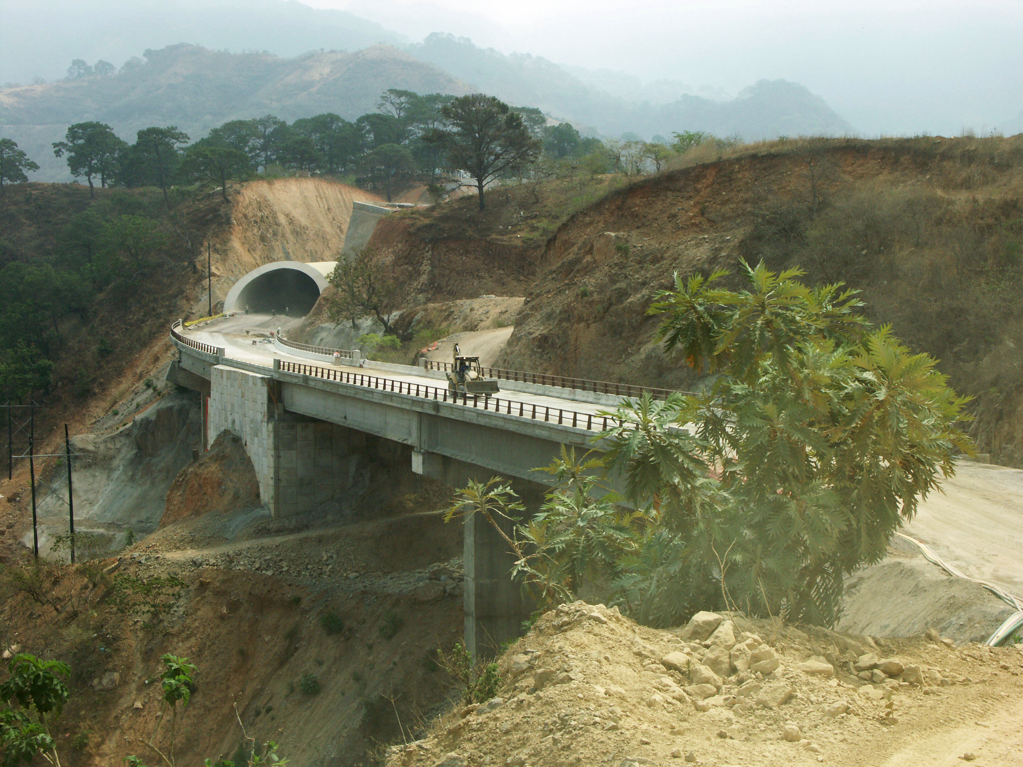
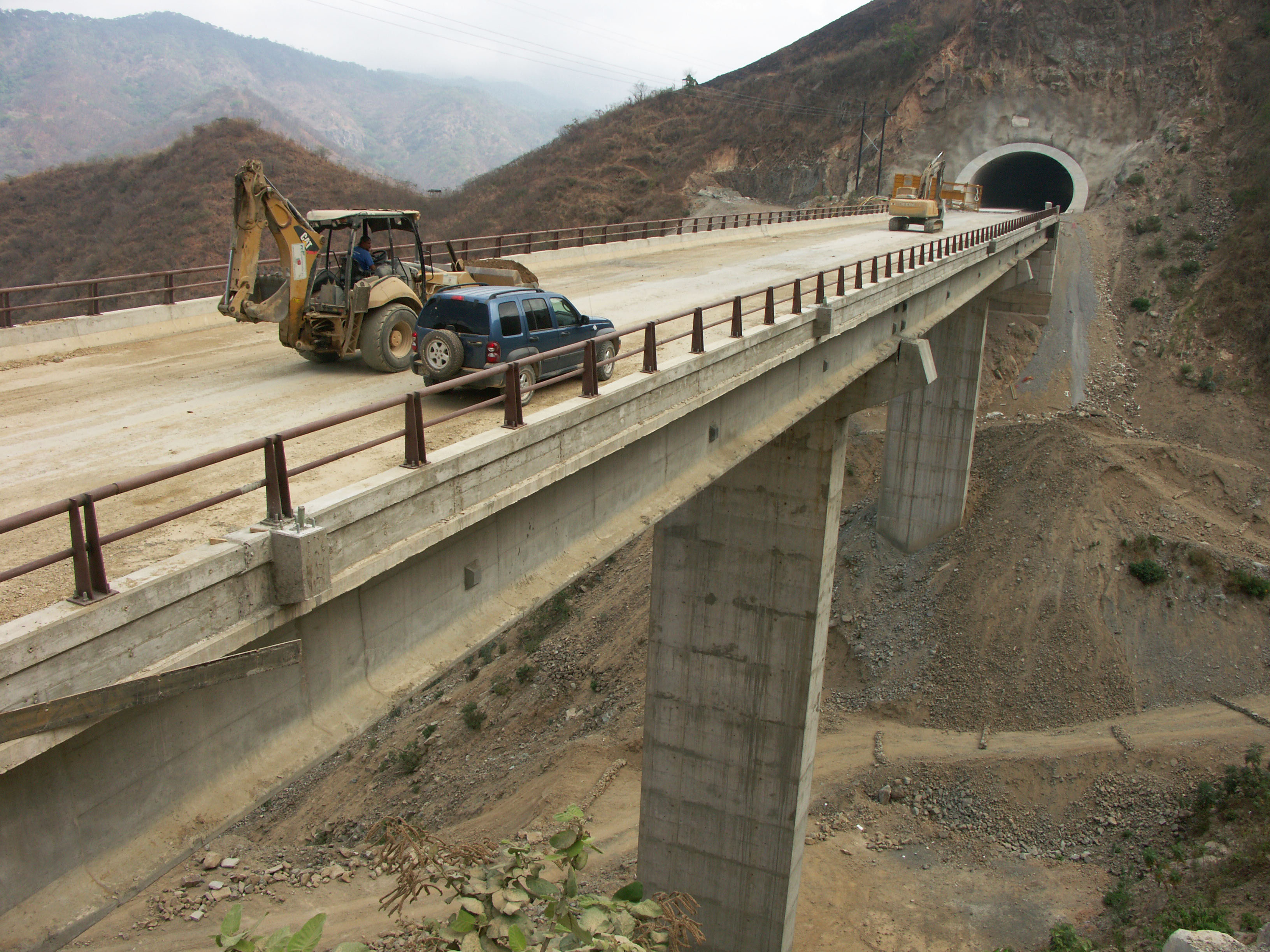
Puente Paso De Piedra en el kilómetro 134. Image by Eric Sakowski / HighestBridges.com
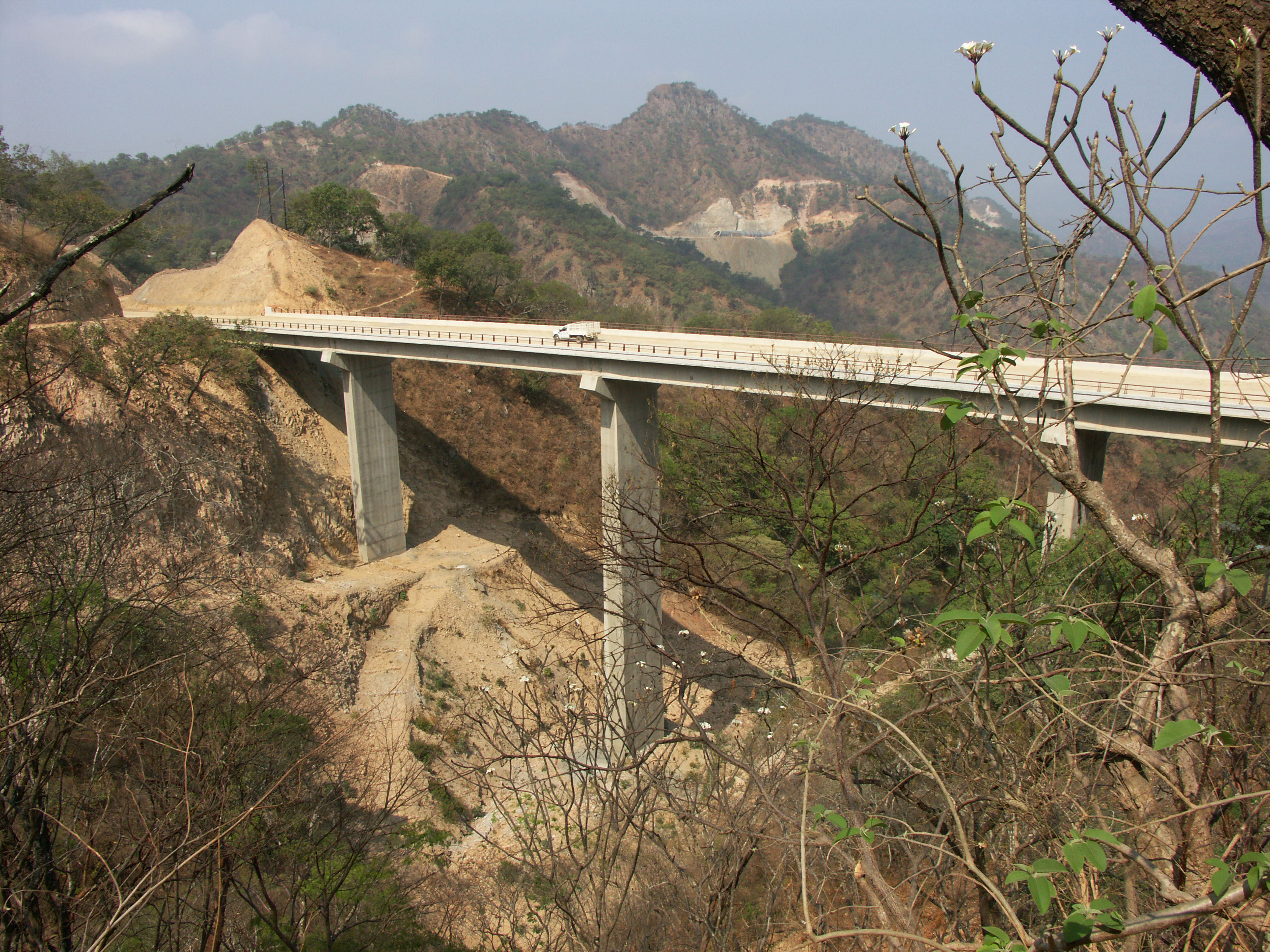
Image by Eric Sakowski / HighestBridges.com
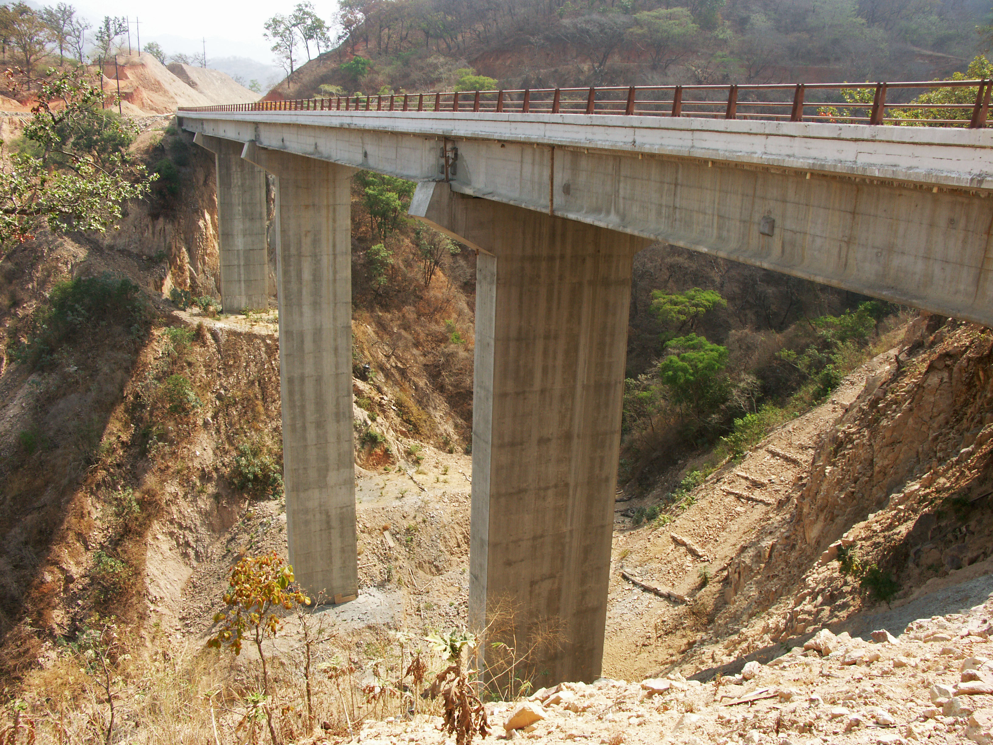
Image by Eric Sakowski / HighestBridges.com
Image by Eric Sakowski / HighestBridges.com
Puentes en los kilómetros 135 - 148
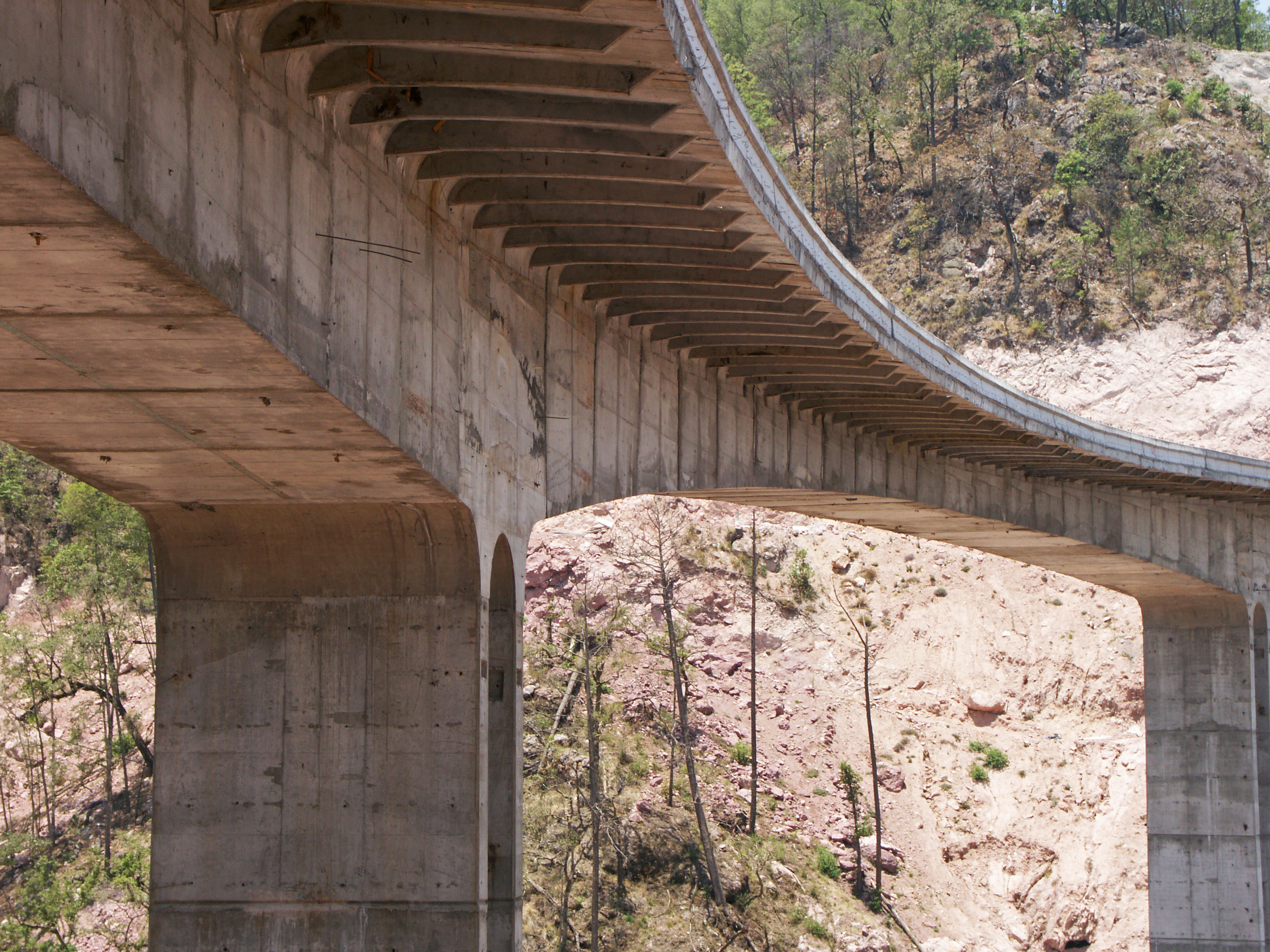
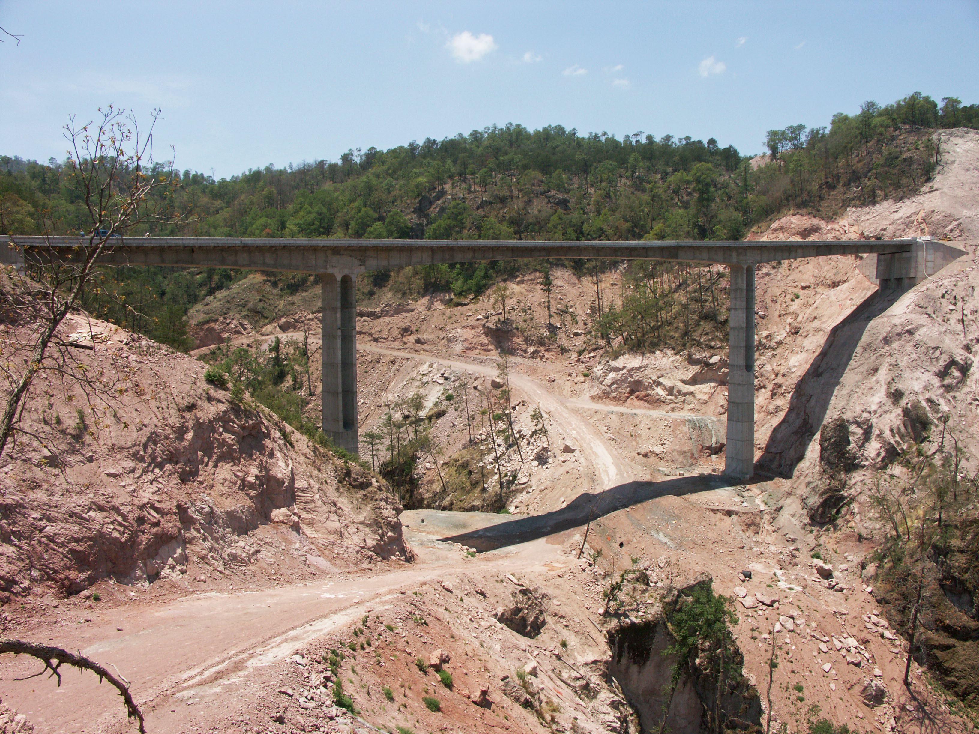
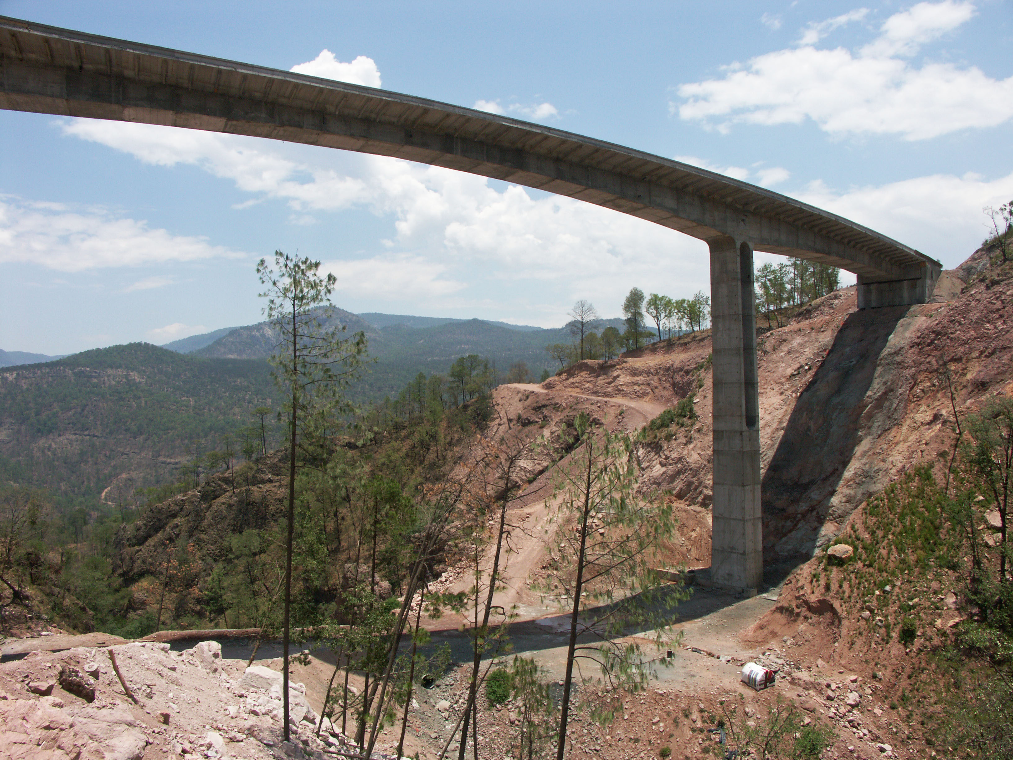
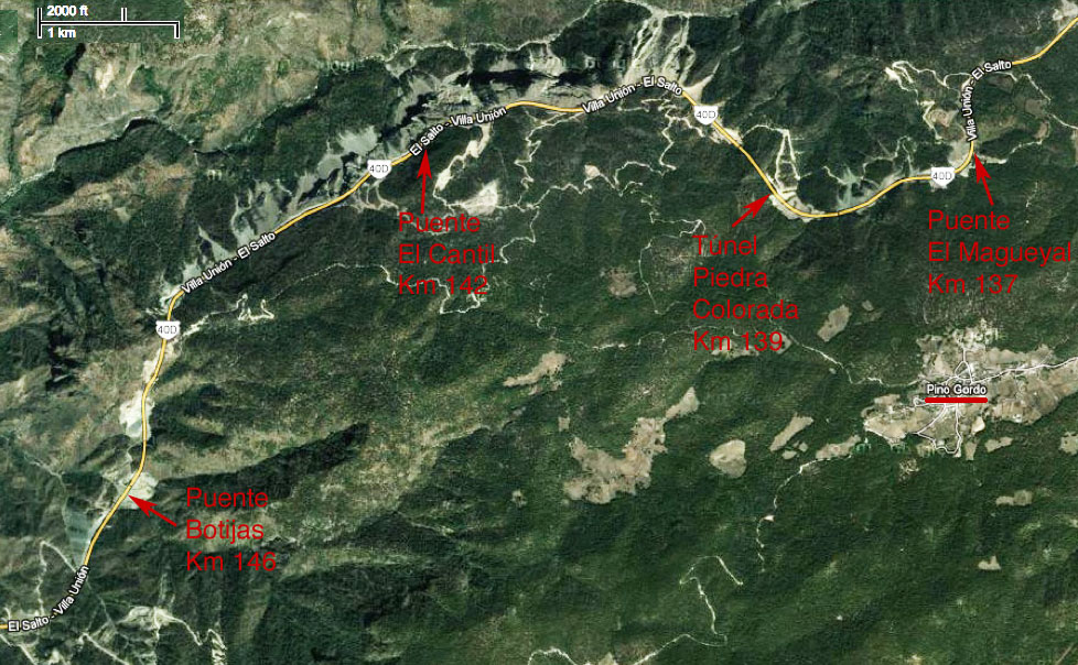
Puente El Magueyal en el kilómetro 137. El puente cuenta con 3 claros de 31.5, 42 y 31.5 metros. Image by Eric Sakowski / HighestBridges.com
Puente El Magueyal en construcción. Image by SCT
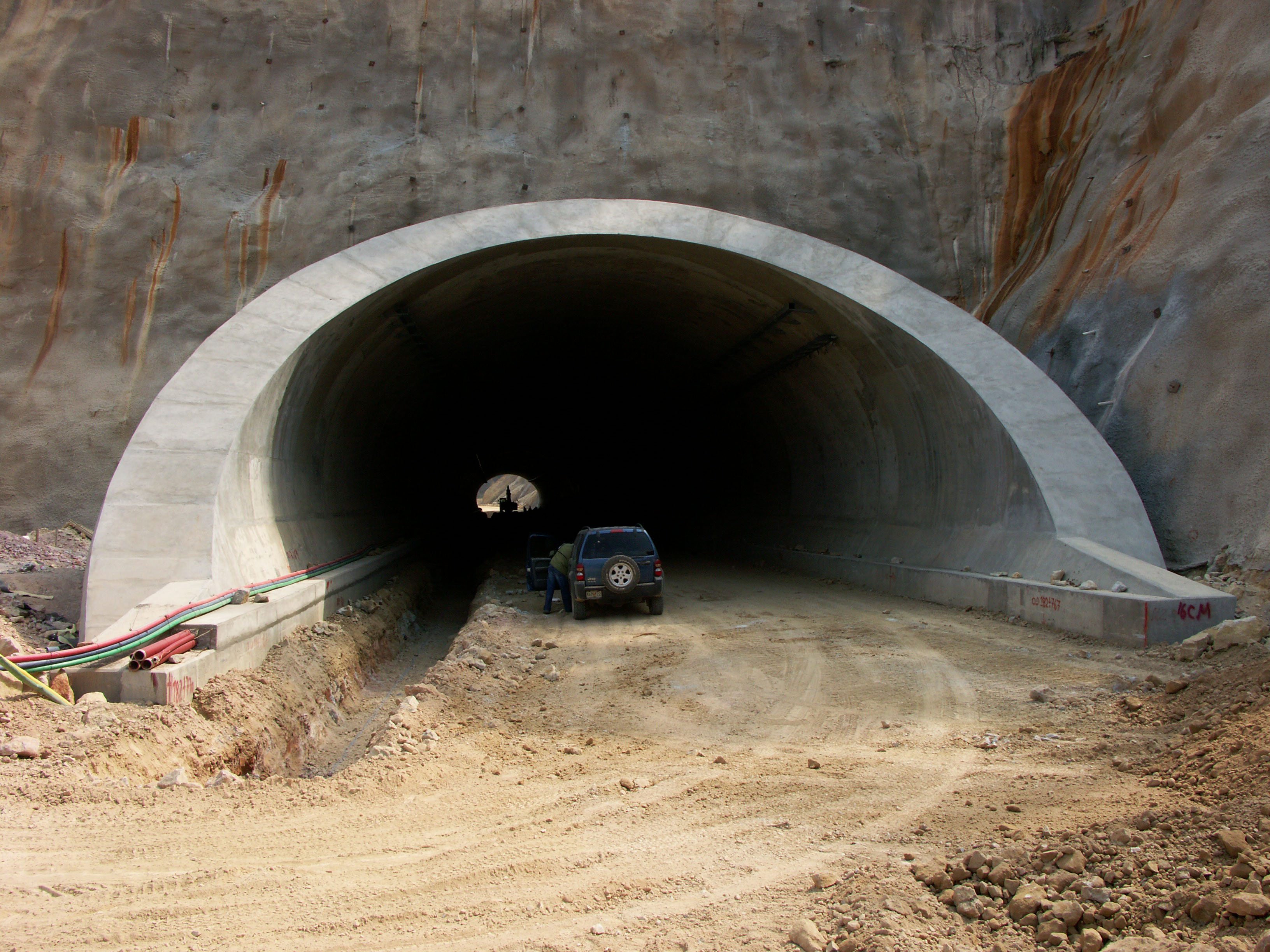
Túnel Piedra Colorada. Image by Eric Sakowski / HighestBridges.com
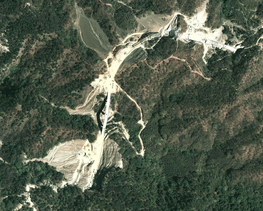
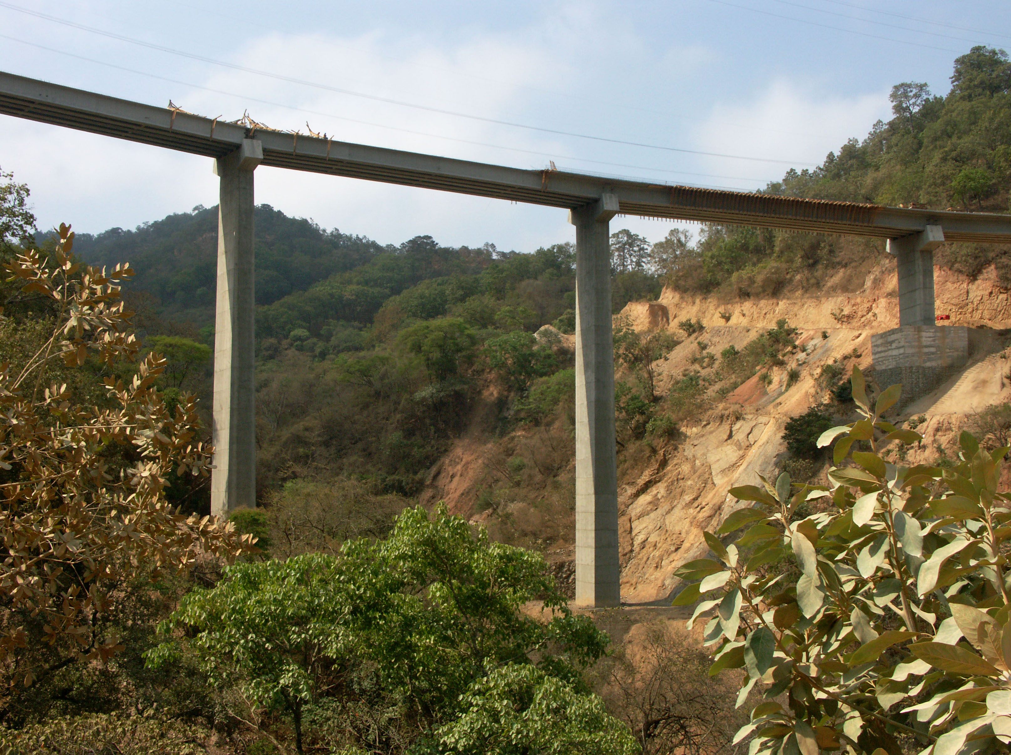
Puente El Cantil en el kilómetro 142. Image by Eric Sakowski / HighestBridges.com
Imagen satelital del puente El Cantil.
Image by Eric Sakowski / HighestBridges.com
Image by Eric Sakowski / HighestBridges.com
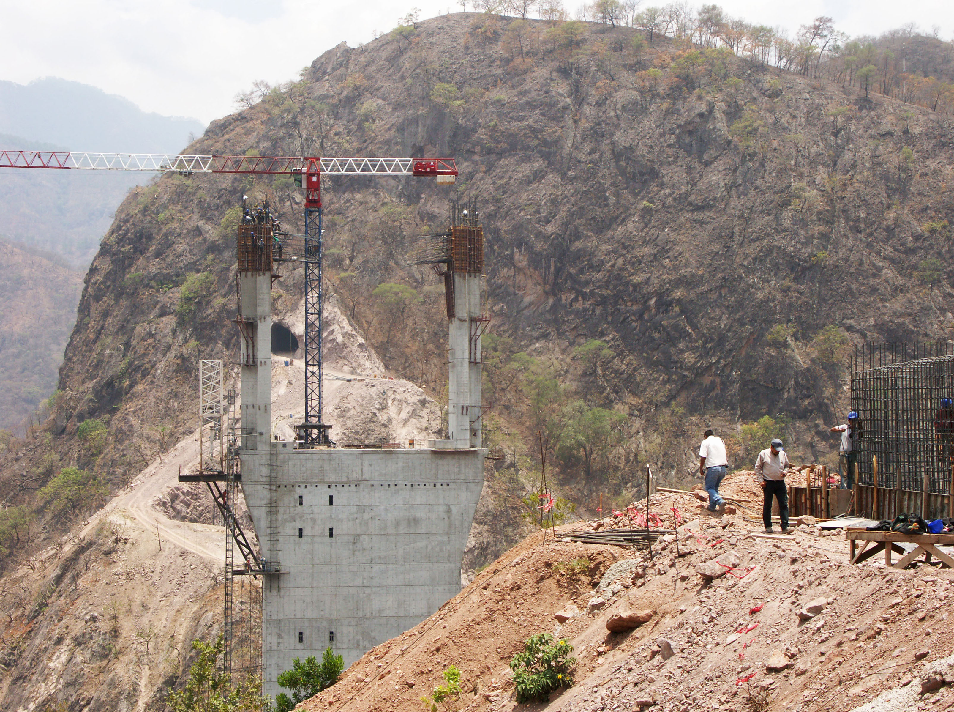
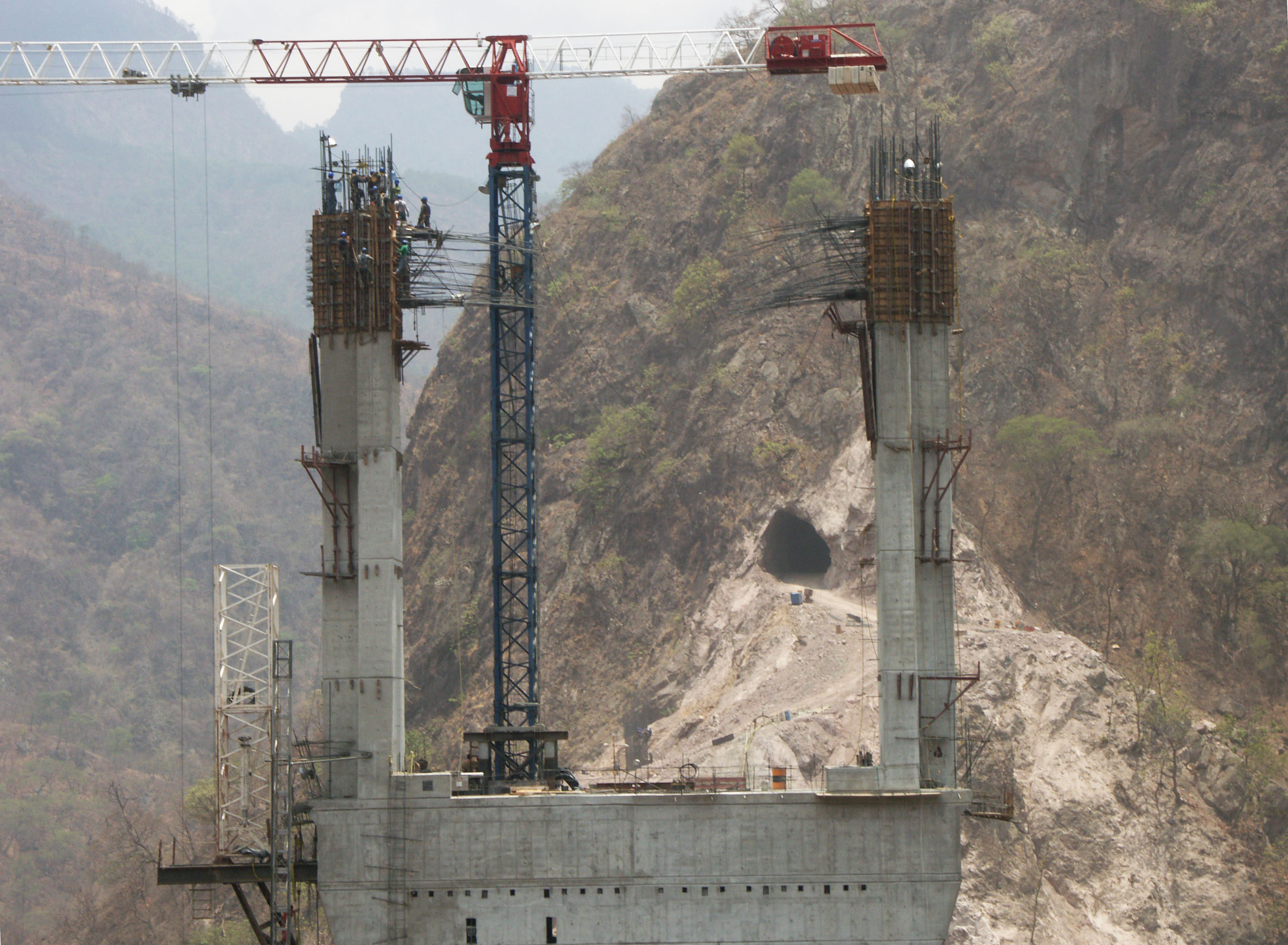
Túneles El Frijolar y Tortuga en el kilómetro 145. La construcción temprana del Puente Botijas se puede ver enfrente de la entrada del túnel El Frijolar.
Early construction of Botijas Bridge can be seen in front of the tunnel entrance of El Frijolar. Image by SCT
Entrada del túnel El Frijolar. Image by SCT
Diagrama del anclaje en roca del túnel El Frijolar pared de roca ancla.
El Frijolar tunnel rock anchor diagram. Image by SCT
Puente Botijas en el kilómetro 146. El puente cuenta con 3 claros de 82.5, 165 y 82.5 metros. Image by Eric Sakowski / HighestBridges.com
Puente Botijas. Image by Eric Sakowski / HighestBridges.com
¡Una familia disfruta del puente Botijas! Image by Eric Sakowski / HighestBridges.com
Image by Eric Sakowski / HighestBridges.com
El puente Botijas tiene la longitud de claro más larga y es también el puente viga más alto de la carretera.
Botijas Bridge has the longest beam span and is also the highest beam bridge on the carretera. Image by Eric Sakowski / HighestBridges.com
Image by Eric Sakowski / HighestBridges.com
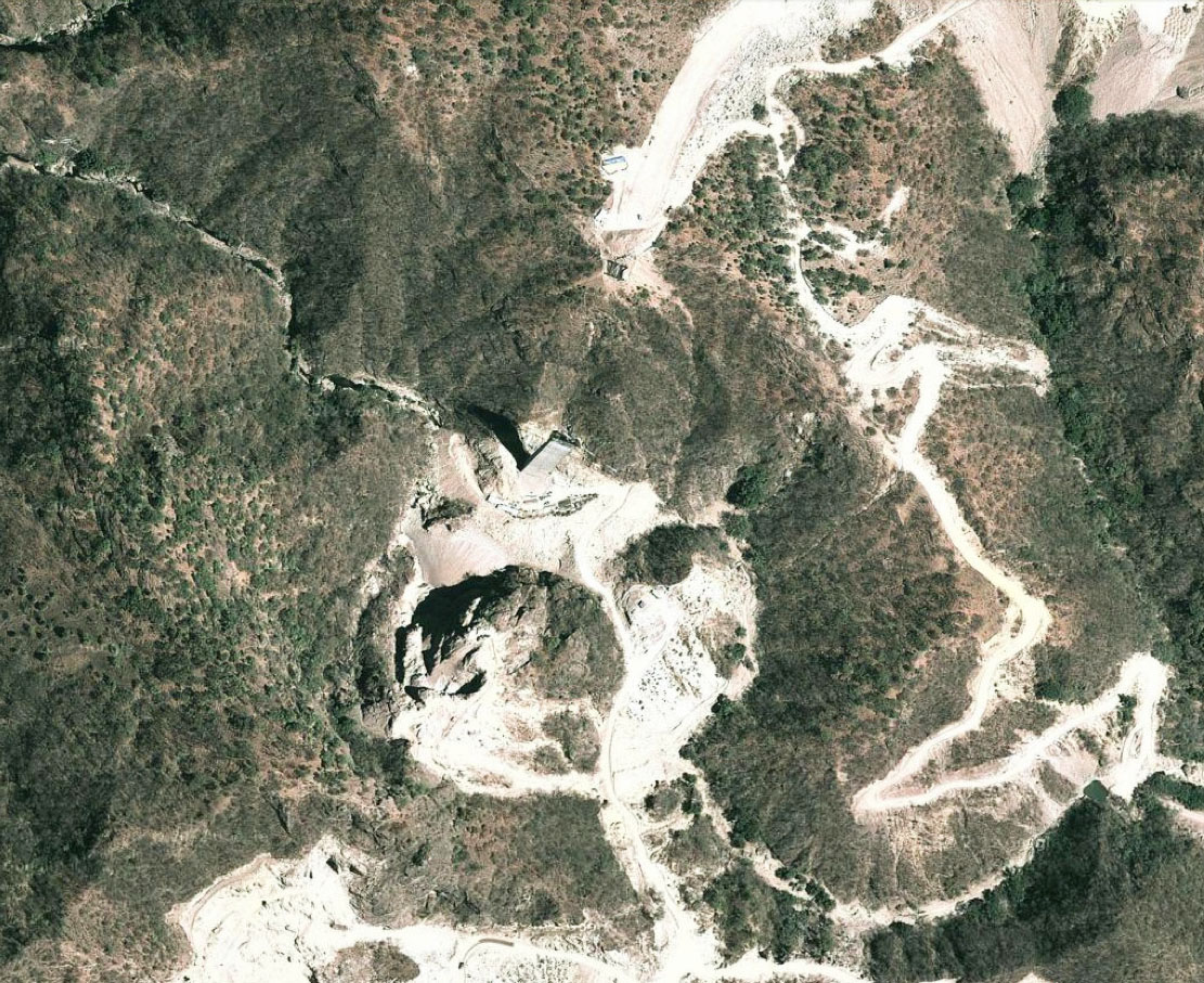
Puente Botijas satélite.
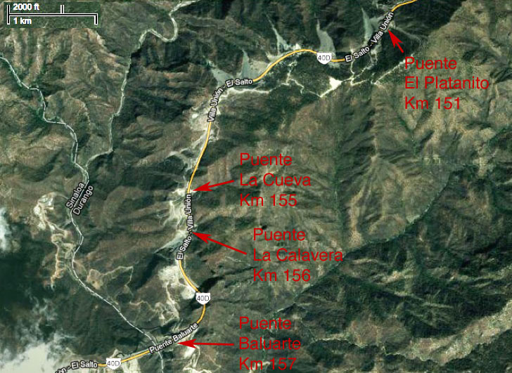
Puentes en los kilómetros 150 - 157
Puente Platanito en el kilómetro 146. Image by SCT
Imagen satelital del Puente Platanito.
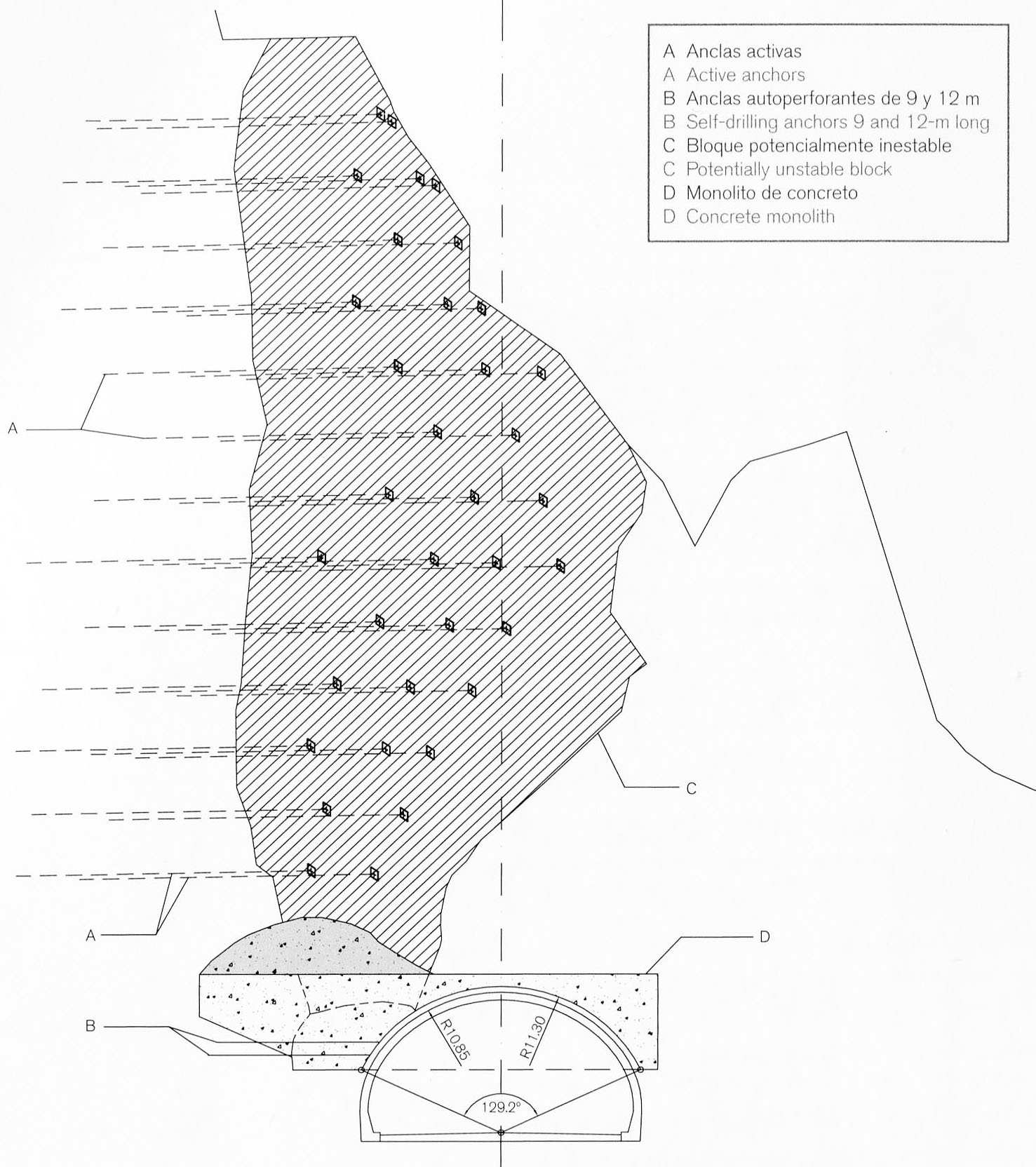
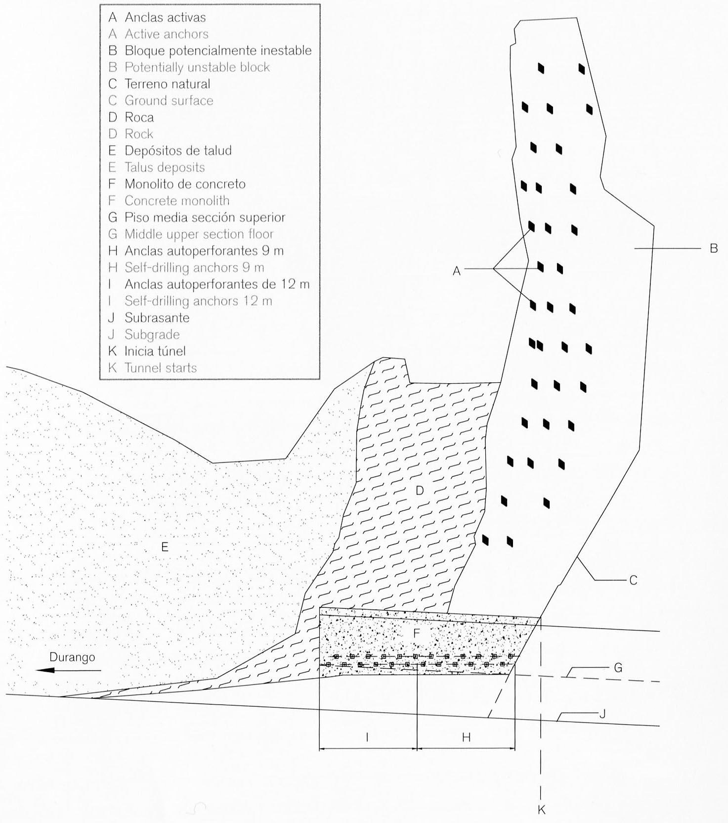
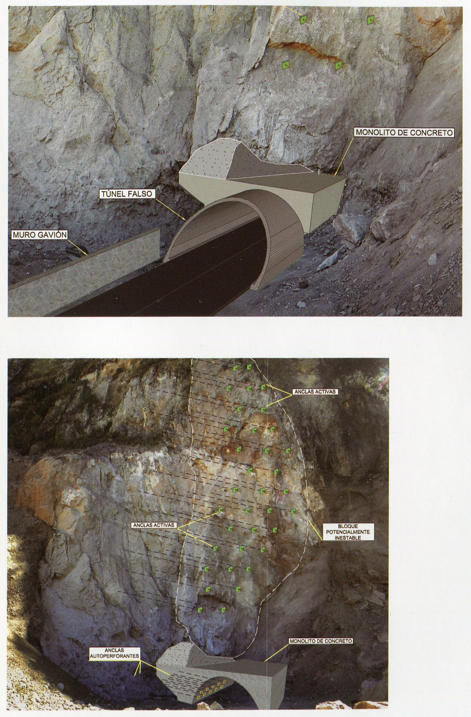
Una de las portales de túneles más difíciles fue la entrada del túnel Baluarte en el lado de Durango. Un bloque de 20,000 toneladas cayó en el portal delantero, lo que obligó a los ingenieros a mover el portal de entrada 8 metros a la derecha, así como el uso de anclas de tensión de 25 metros de largo en un patrón escalonado de 5 x 5 metros en la ladera.
One of the most difficult tunnel portals was the Durango entrance of the Baluarte tunnel. A 20,000 ton block crashed down at the front portal and required the engineers to move the portal entrance 8 meters to the right as well as using 25 meter long tension anchors in a staggered pattern of 5 x 5 meters on the slope. Image by SCT
Túnel Baluarte. Image by SCT
Túnel Baluarte. Image by SCT
Puente Baluarte -
¡El puente más alto en la carretera Durango-Mazatlán!
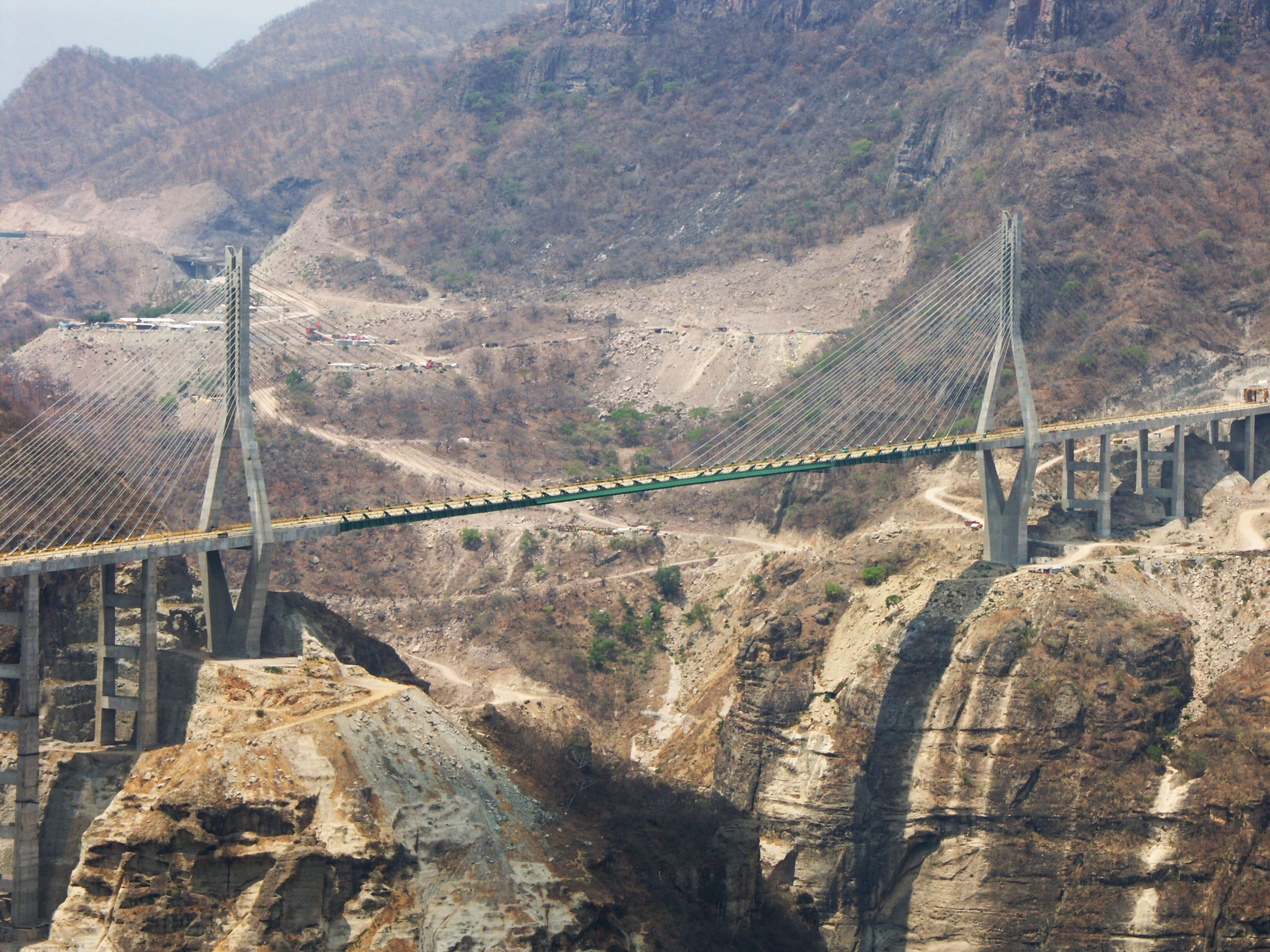
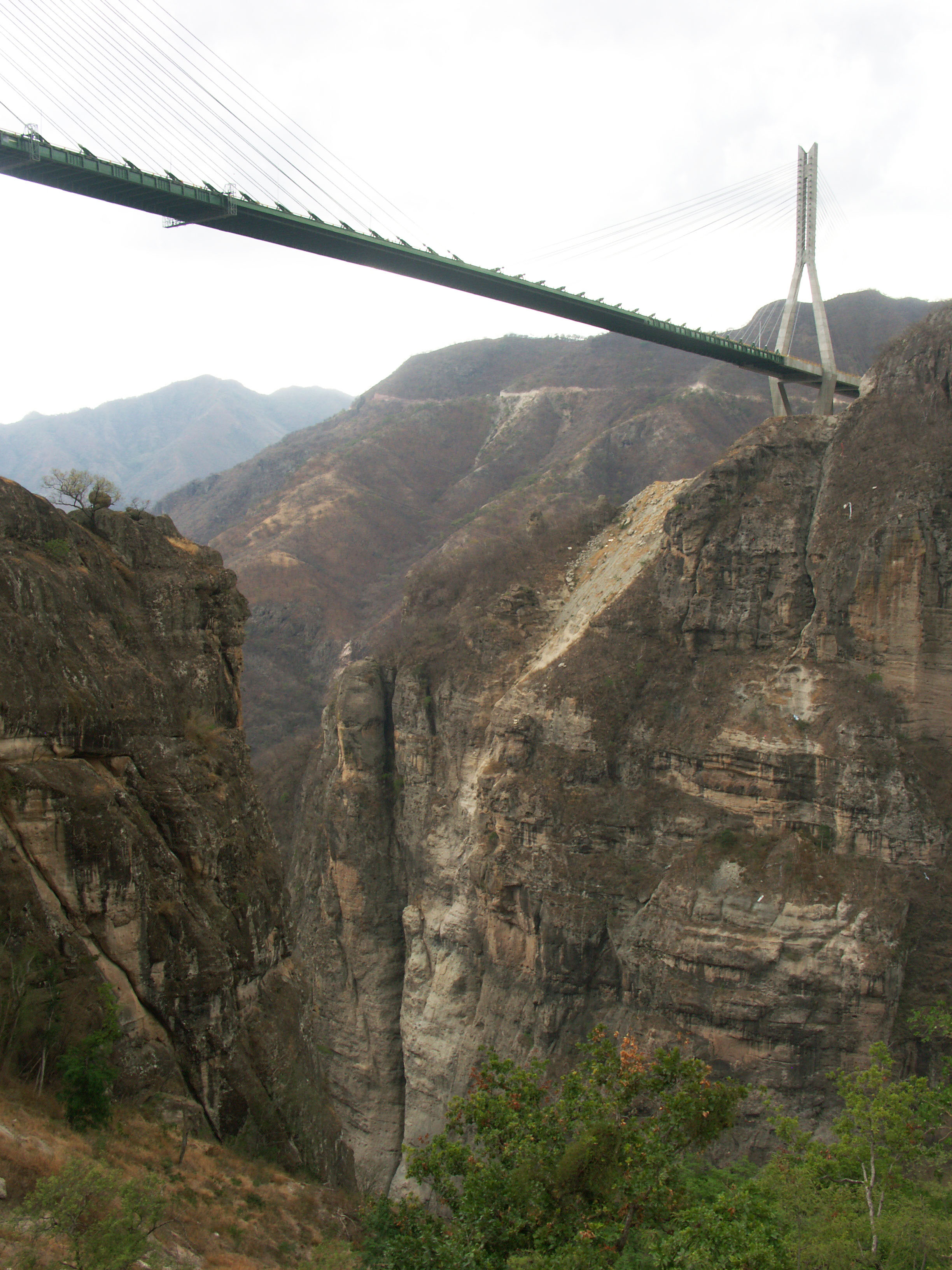
El gran puente Baluarte en el kilómetro 157. El más alto en el continente americano, con una altura de 390 metros. Image by Eric Sakowski / HighestBridges.com
Image by Eric Sakowski / HighestBridges.com
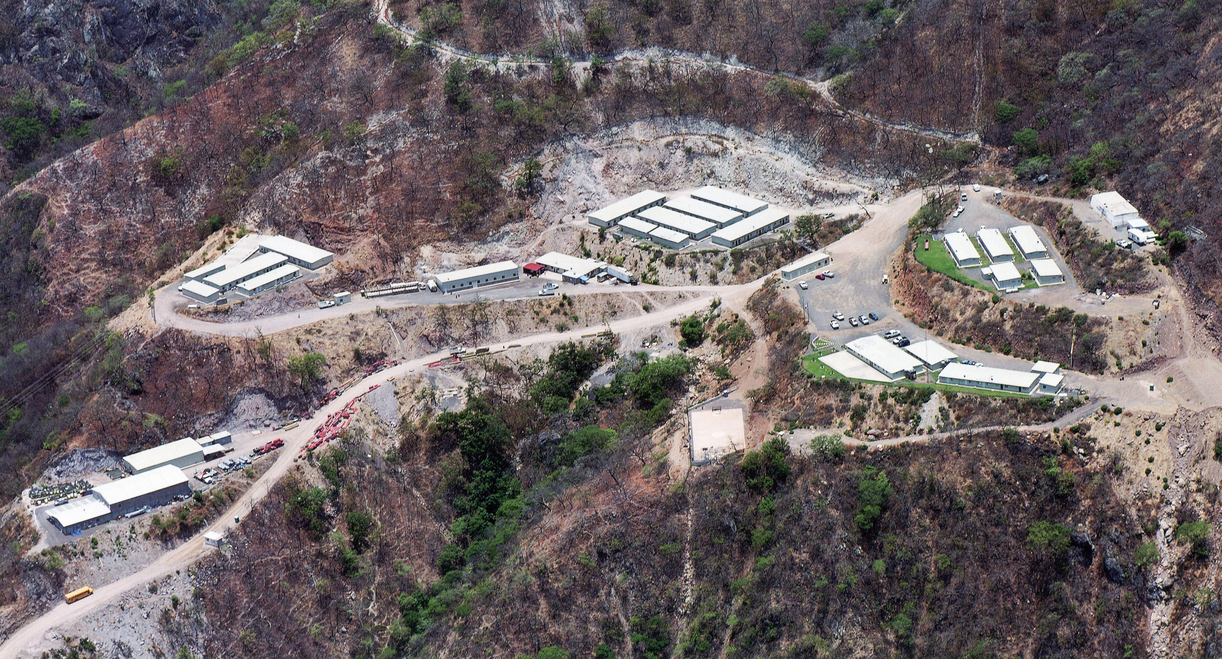
Vivienda para los trabajadores y oficinas para la construcción del puente Baluarte.
Worker housing and headquarters for the Baluarte bridge construction. Image by SCT
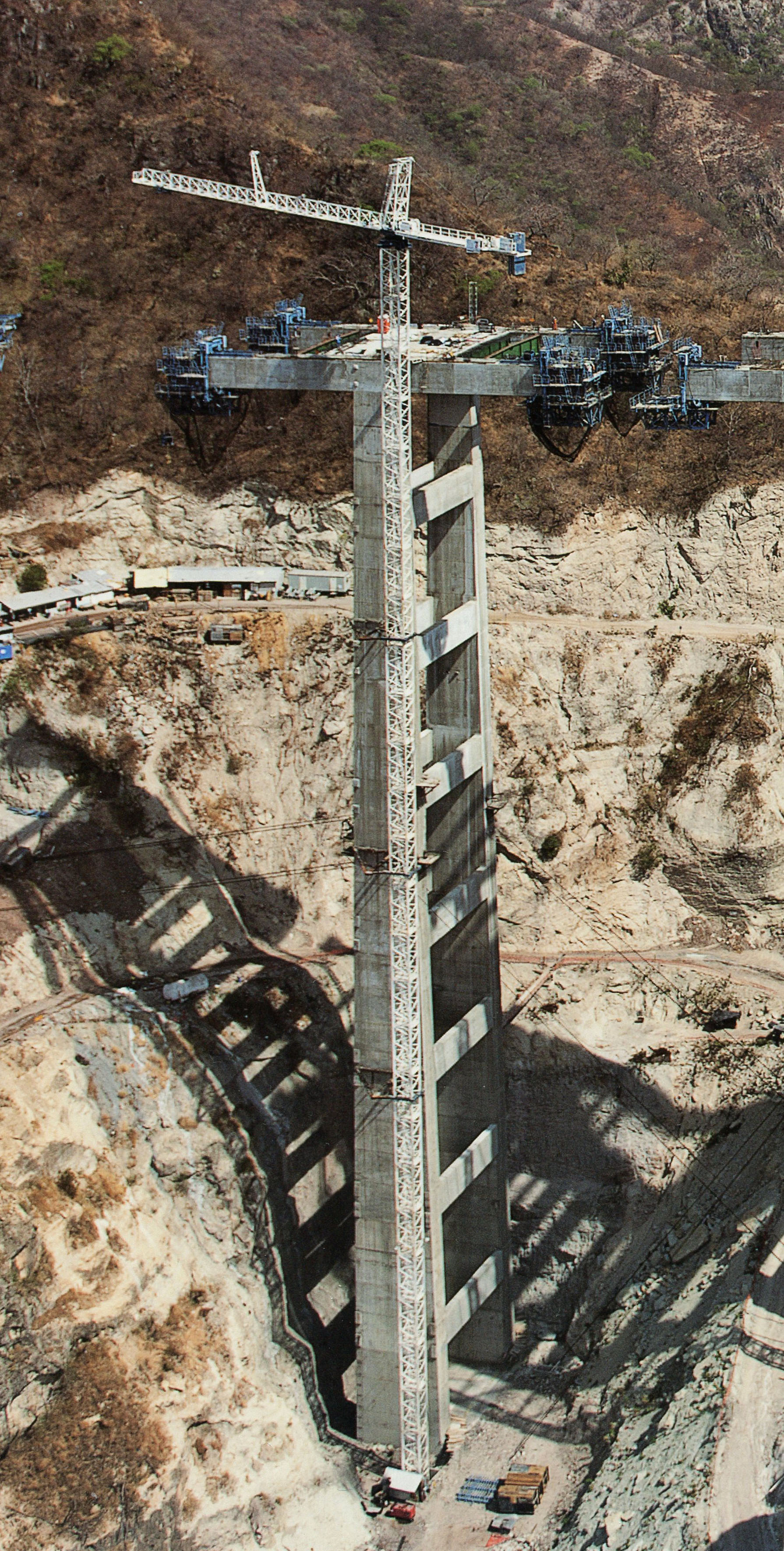
La pila 9 del puente Baluarte está a 140 metros de altura. Image by SCT
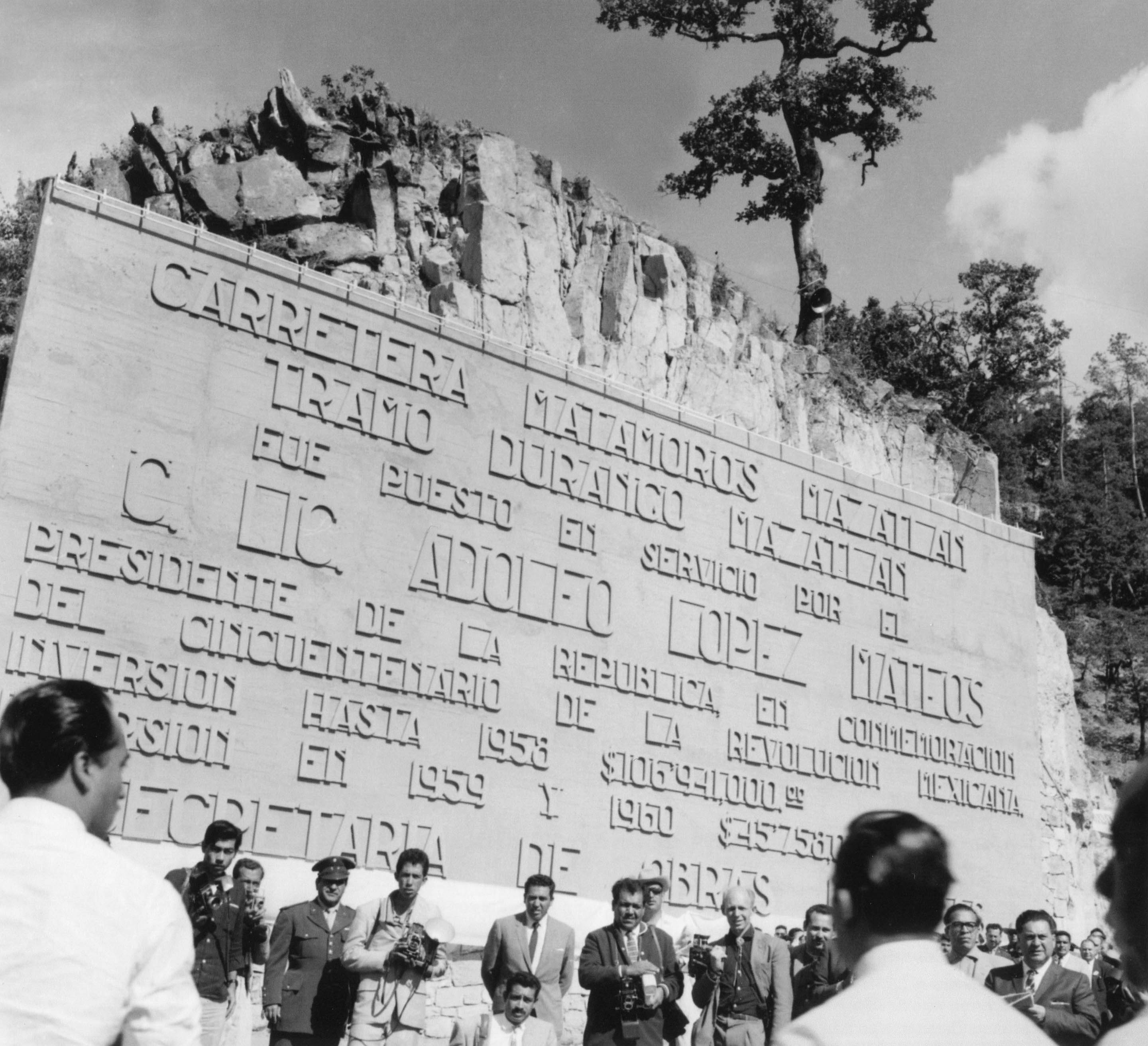
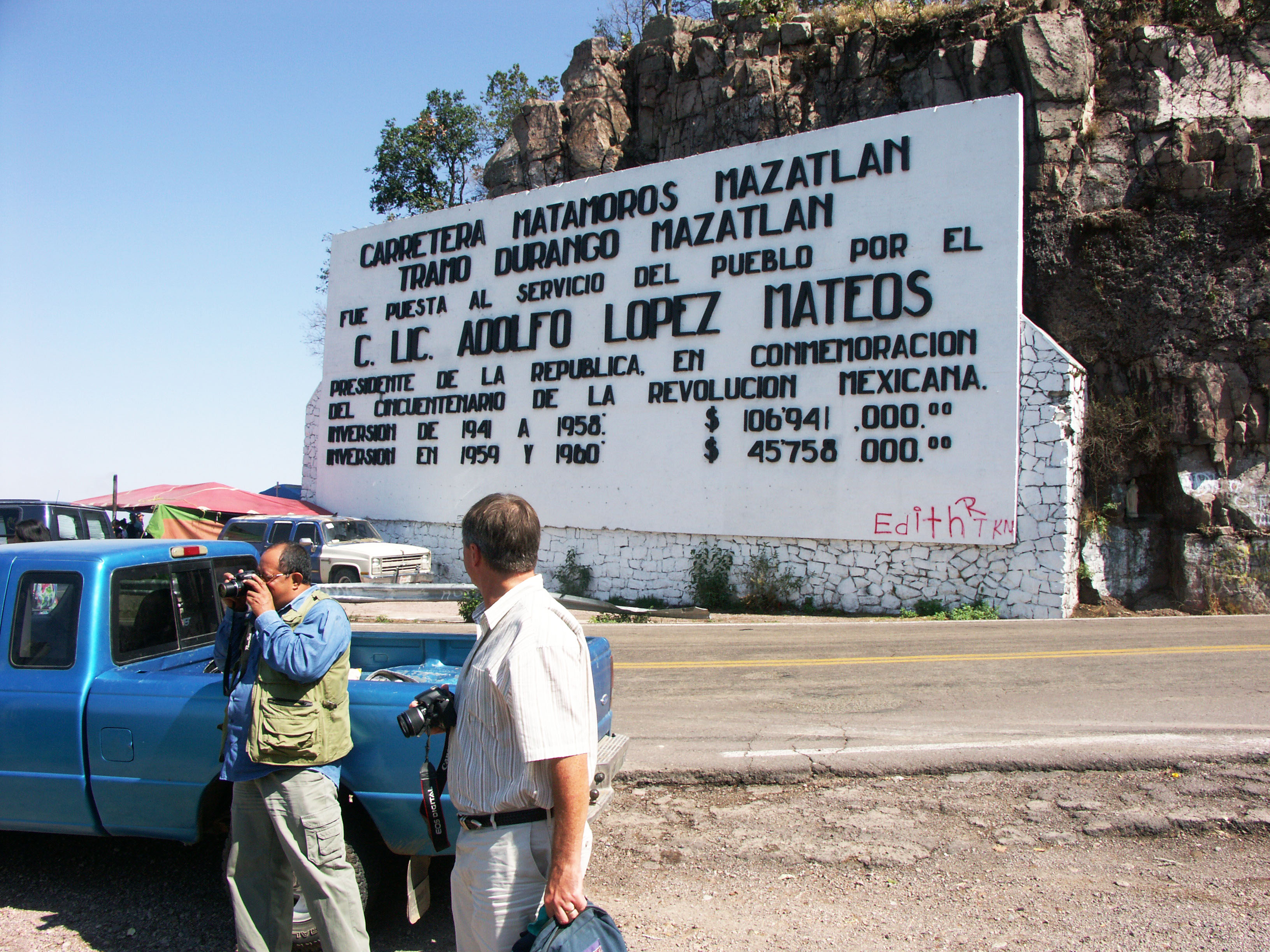
Signo del Espinazo del Diablo y la inauguración de la carretera antigua en 1960 con el presidente Adolfo López Mateos.
Devil's Backbone sign & inauguration in 1960 with Presidente Adolfo López Mateos. Image by SCT
Image by Eric Sakowski / HighestBridges.com
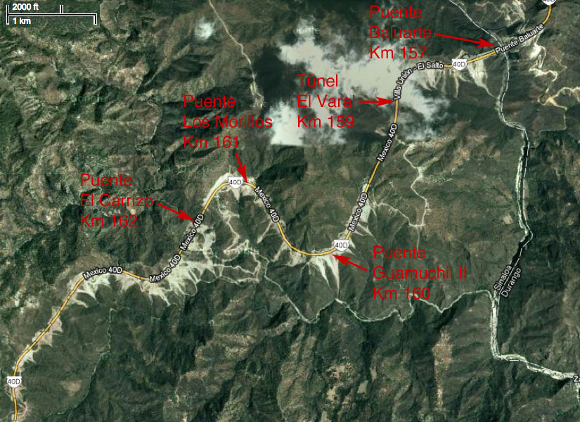
Puentes en los kilómetros 157 - 166
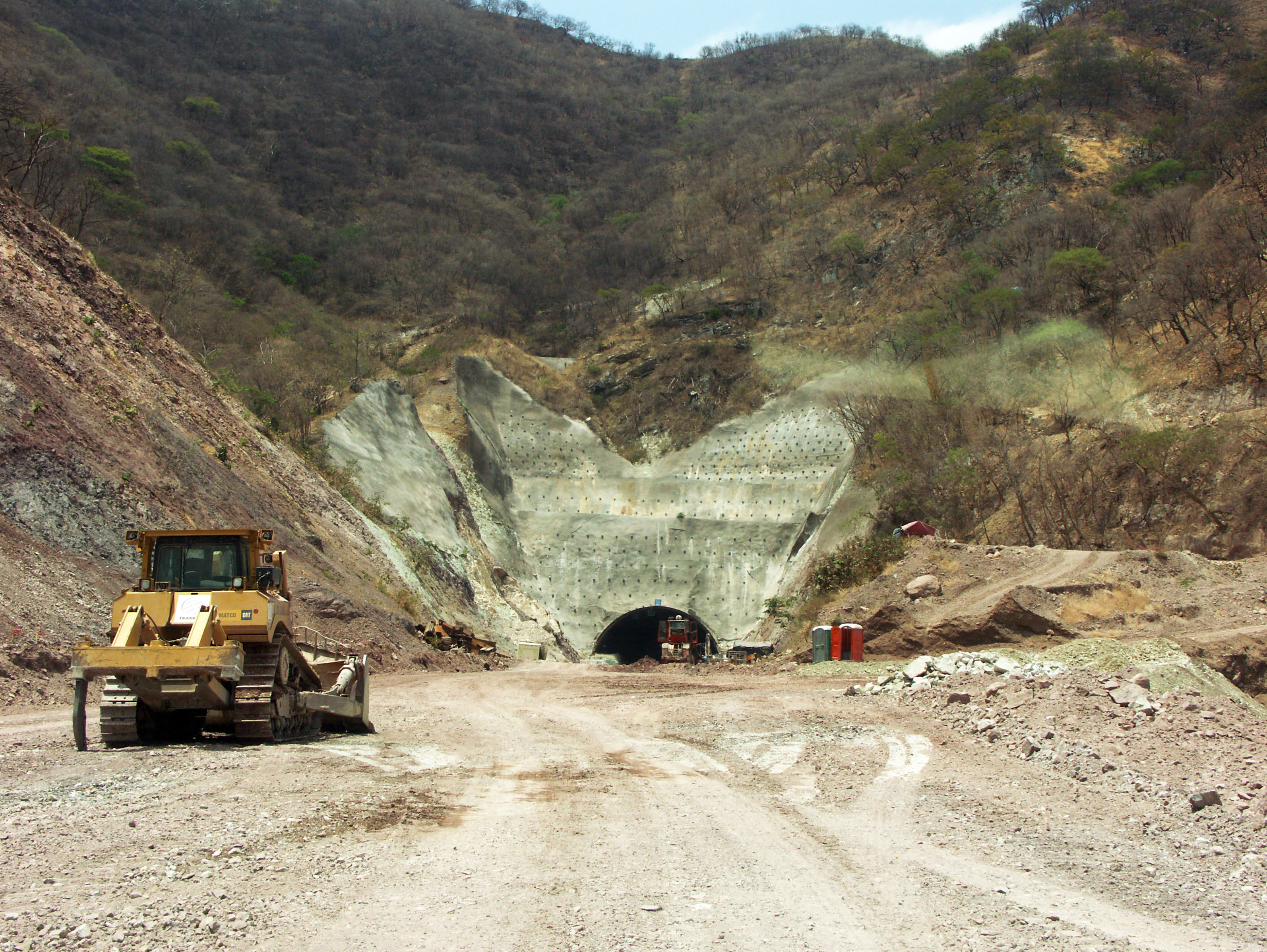
Túnel El Varal en el kilómetro 160. Image by Eric Sakowski / HighestBridges.com
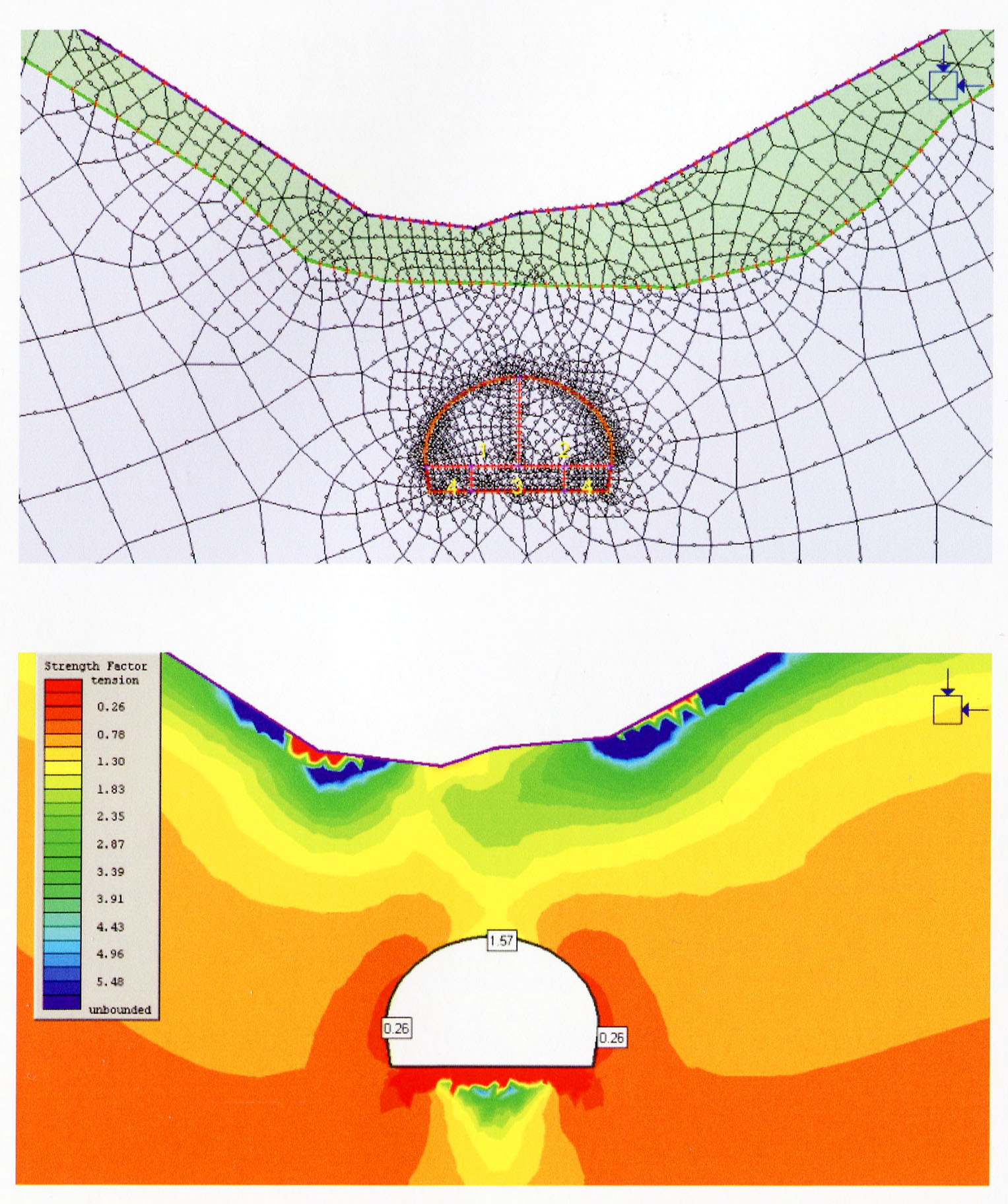
Modelado de malla y diagrama de esfuerzo de la masa de roca circundante al túnel El Varal. Para estimar el peso de una cuña de roca que podría deslizarse hacia el interior de un túnel y debe ser soportada por el revestimiento, los parámetros deben de ser calculados para la carga en puntos clave, la anchura del túnel, el peso de la roca, la cohesión del sistema de fracturas encima de puntos clave del túnel, la relación entre las tensiones horizontal y vertical, la profundidad del túnel y el ángulo de fricción encima de puntos clave del túnel.
Mesh modeling and stress diagram of the rock mass surrounding El Varal tunnel. To estimate the weight of a rock wedge that could slide towards the inside of a tunnel and must be supported by the lining, parameters must be calculated for rock surcharge at the key, the width of the tunnel, the unit weight of the rock, the cohesion of the fracture system immediately above the key of the tunnel, the ratio between horizontal and vertical stresses, the depth of the tunnel and the angle of friction immediately above the key of the tunnel. Image by SCT
Puente Guamuchil I en el kilómetro 160. El puente cuenta con 6 claros: uno 28.5, 4 de 38 y uno de 28.5 metros.Image by Eric Sakowski / HighestBridges.com
Puente Guamúchil II en el kilómetro 160. El puente cuenta con 5 claros de: 49, 95, 49 y 2 de 38 metros. Image by Eric Sakowski / HighestBridges.com
Muchos de los túneles tienen secciones falsas que mantendrán la carretera a salvo de laderas inestables y inestables como el túnel de Guamuchil.
Many of the tunnels have false sections that will keep the highway safe from unstable and steep slopes such as the Guamuchil tunnel. Image by SCT
Puente Los Morillos en el kilómetro 161. El puente cuenta con 4 claros de: 37.5, 50, 50 y 37.5 metros. Image by Eric Sakowski / HighestBridges.com
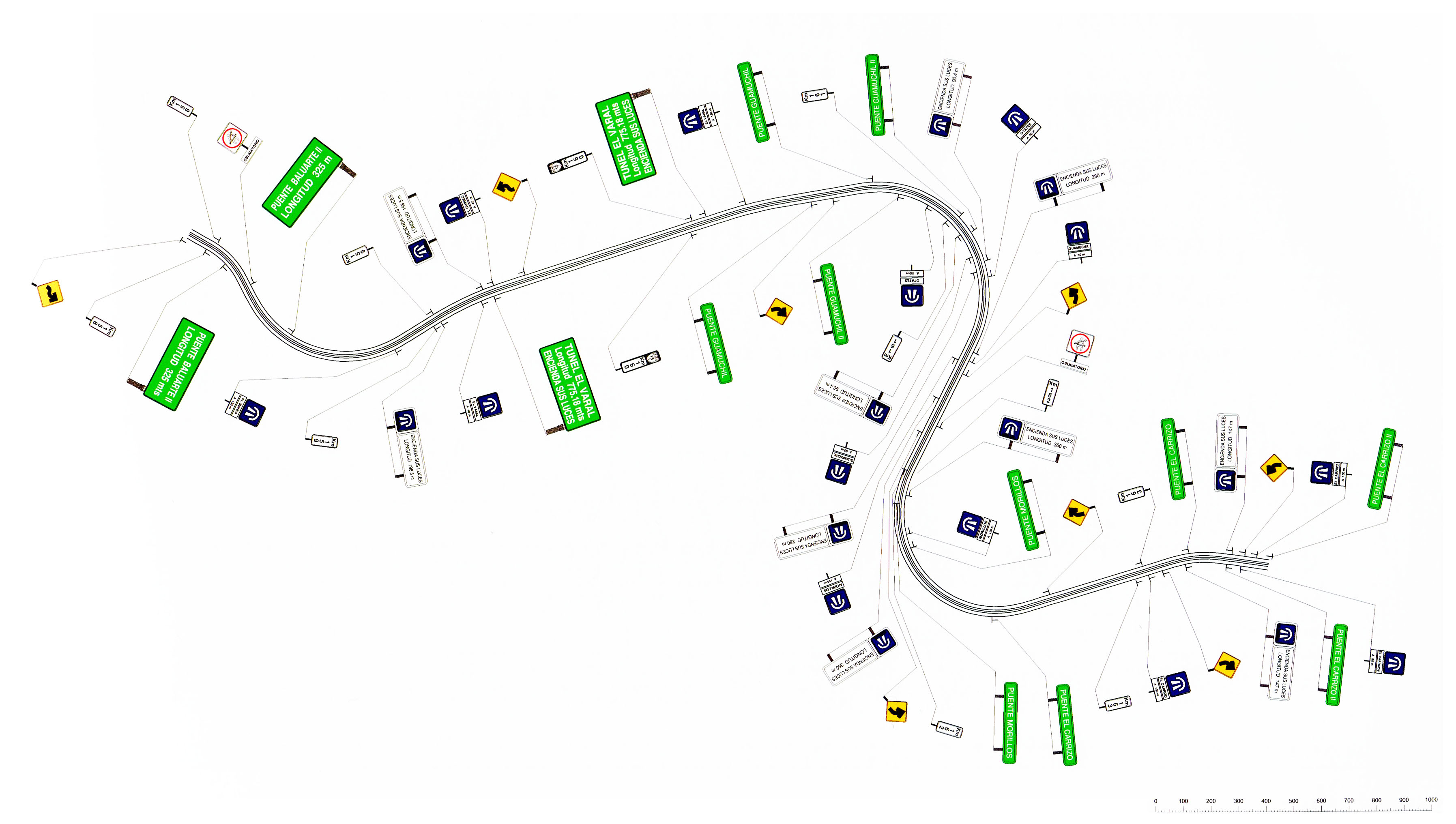
Vista en planta de las señales de tráfico para ser colocadas entre los kilómetros 158 y 168, entre los puentes Baluarte y El Carrizo.
Plan view of traffic signs to be placed between kilometers 158 and 168 between Baluarte and El Carrizo Bridges. Image by SCT
Puente El Carrizo -
¡El Puente con la pila más alta de la carretera Durango Mazatlán!
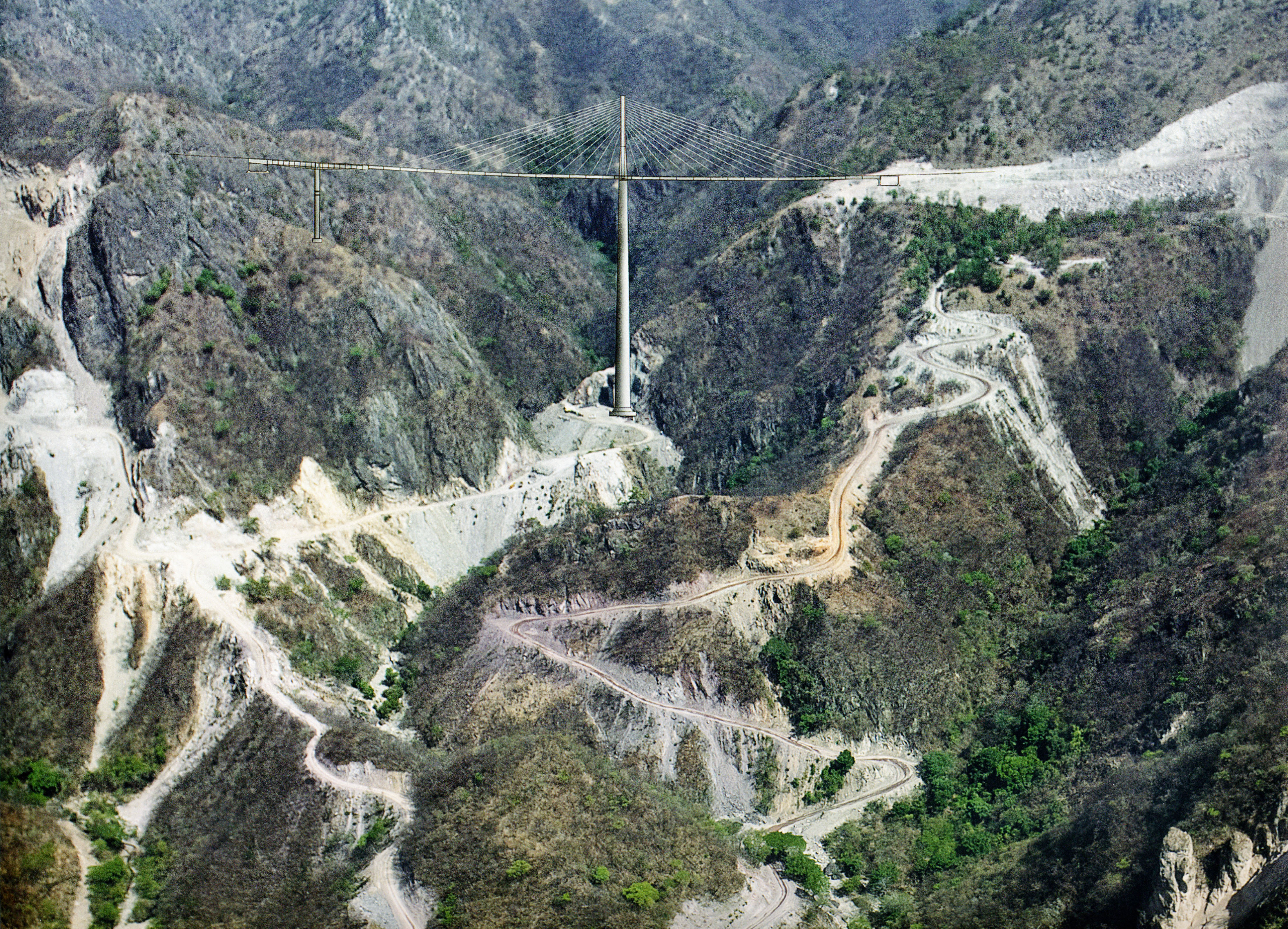
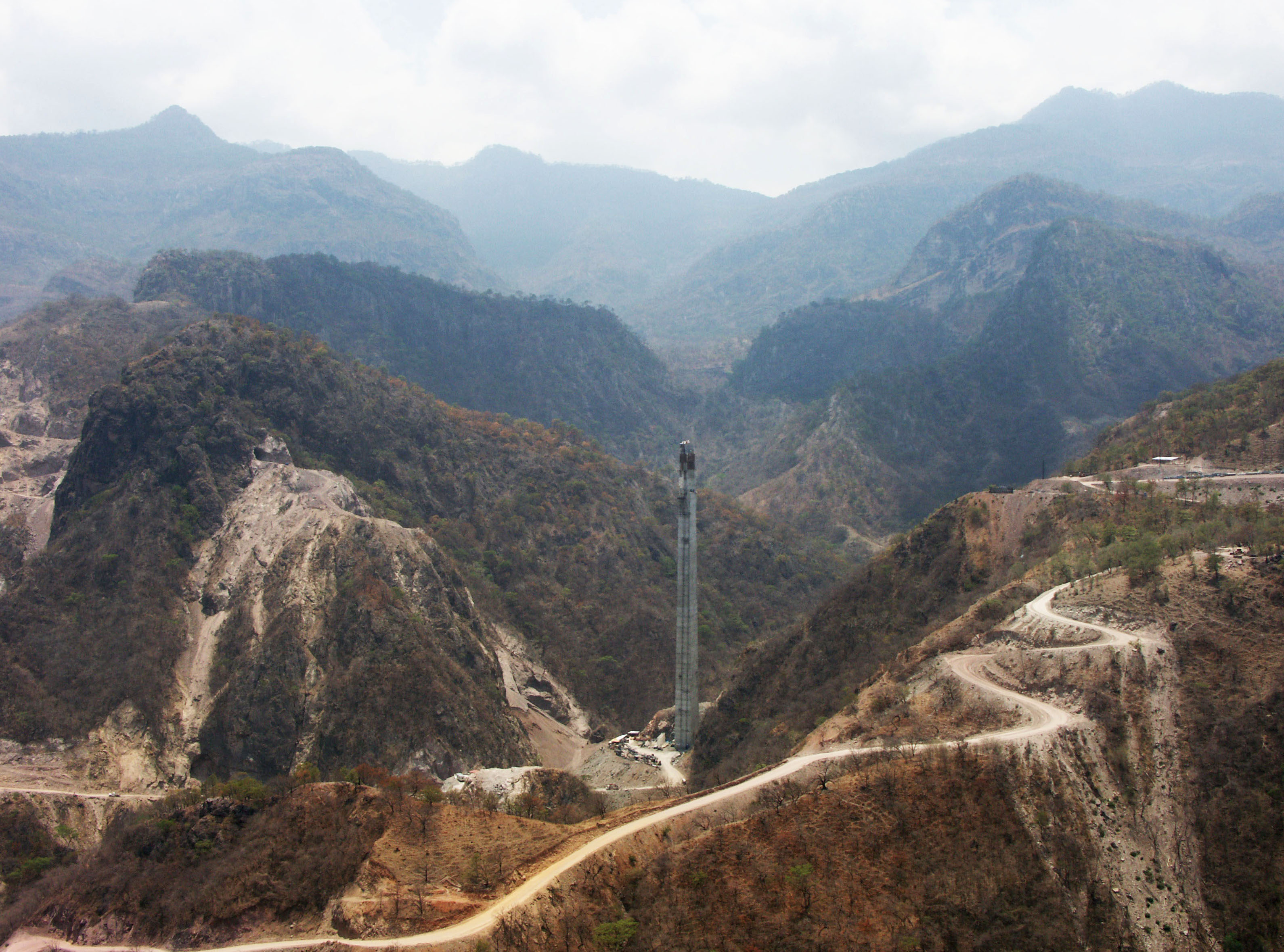
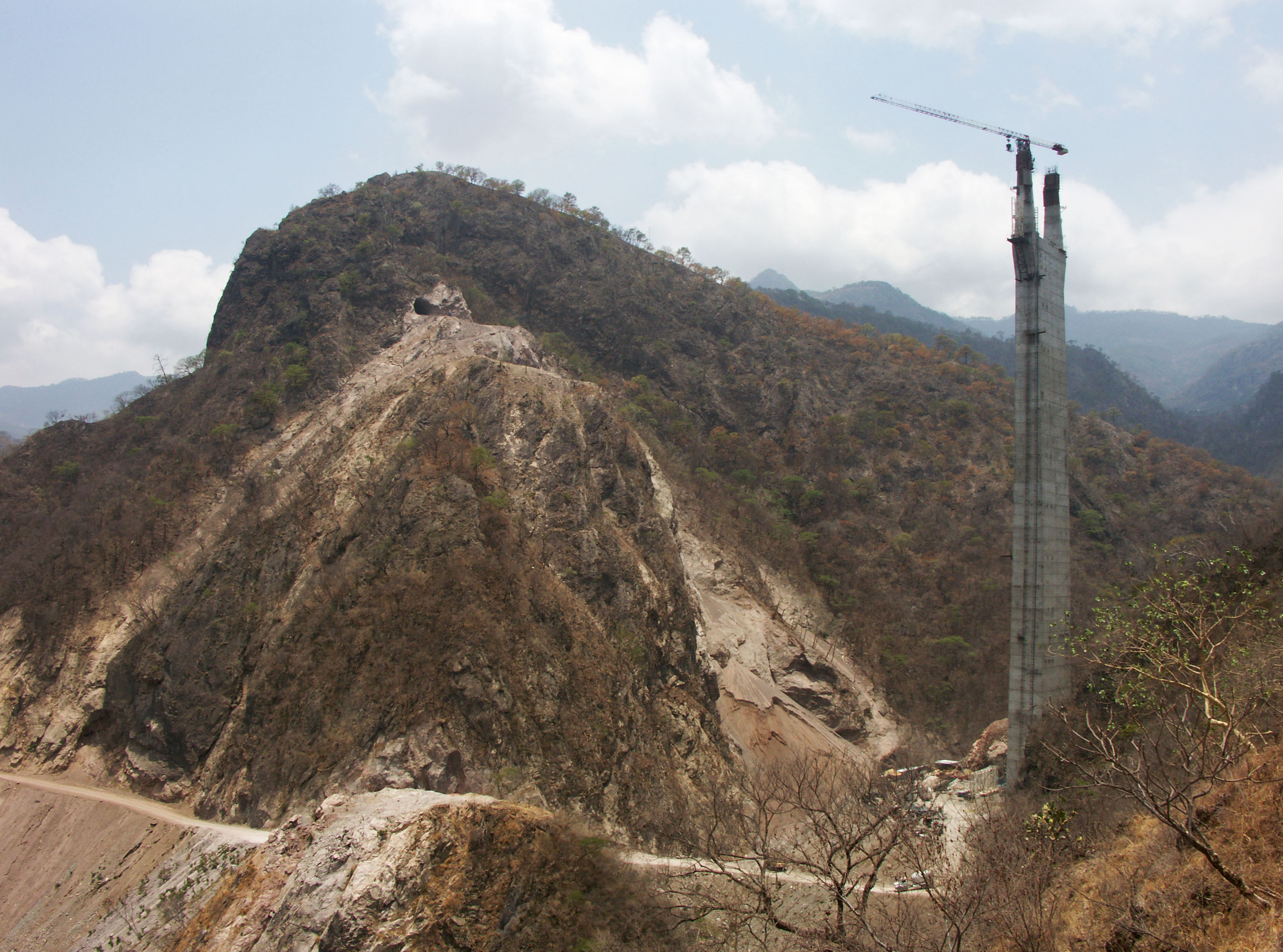
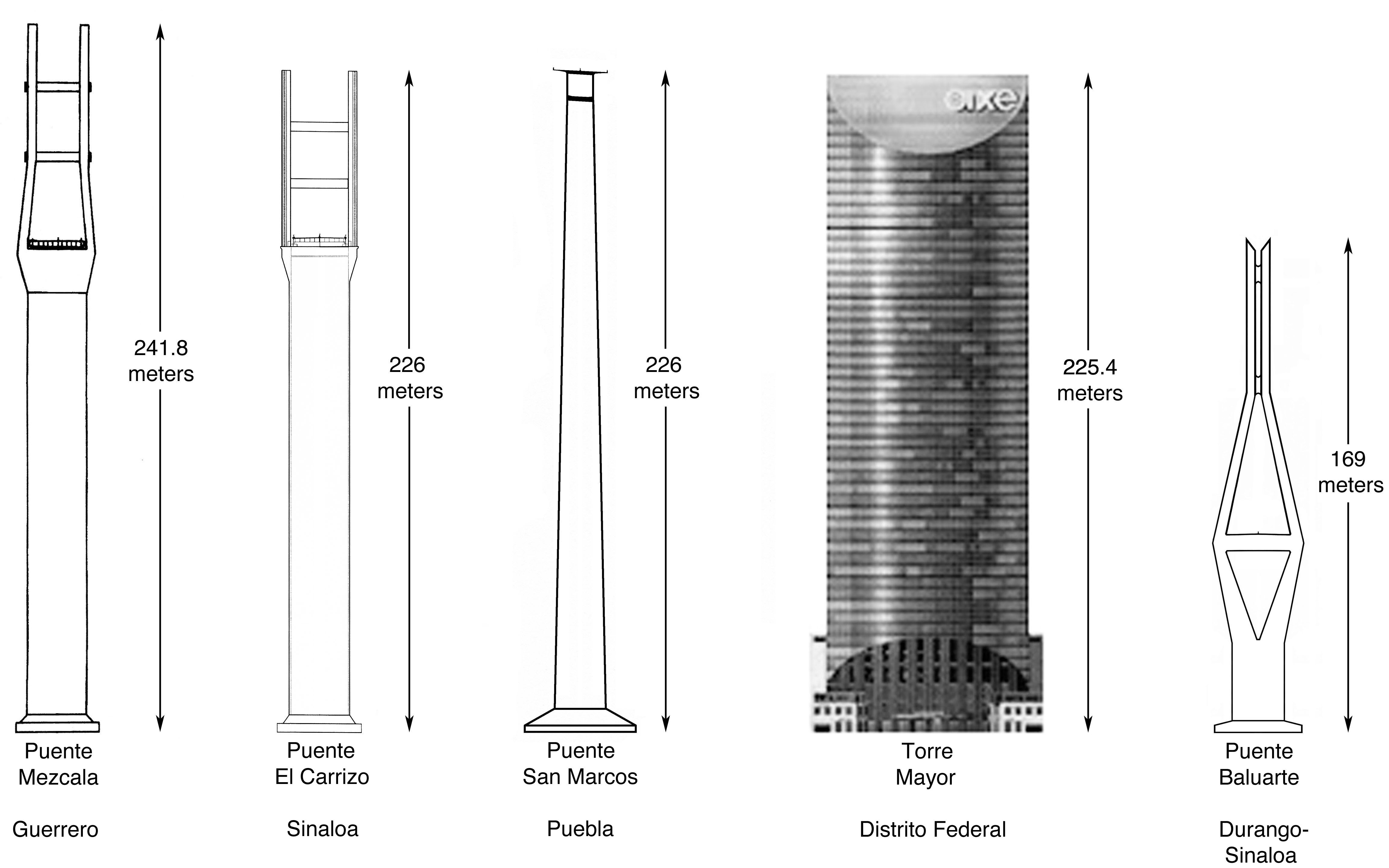
Con tanta atención en la construcción del Puente Baluarte, los medios de comunicación no han prestado mucha atención al segundo puente atirantado de la quebrada El Carrizo ubicado a sólo 5 kilómetros al poniente. Con un mástil central y torre que se eleva a 226 metros, el puente El Carrizo es el más alto de la carretera y la segunda estructura de puente más alta de toda América del Norte después del Puente Mezcala. La estructura es sólo un metro más alta que la Torre Mayor en la Ciudad de México.
Diseño de la elevación del puente El Carrizo sobre una fotografía del área.
With so much attention on the construction of Baluarte Bridge, few in the media have given much attention to the second cable stayed crossing of the El Carrizo gorge located just 5 kilometers west. With a central pier and tower rising 226 meters, the El Carrizo Bridge is the tallest bridge on the highway and the second tallest bridge structure in all of North America after the Mezcala Bridge. The structure is just one meter higher then the Torre Mayor building in Mexico City.
El Carrizo Bridge elevation drawing placed over photograph. Image by SCT
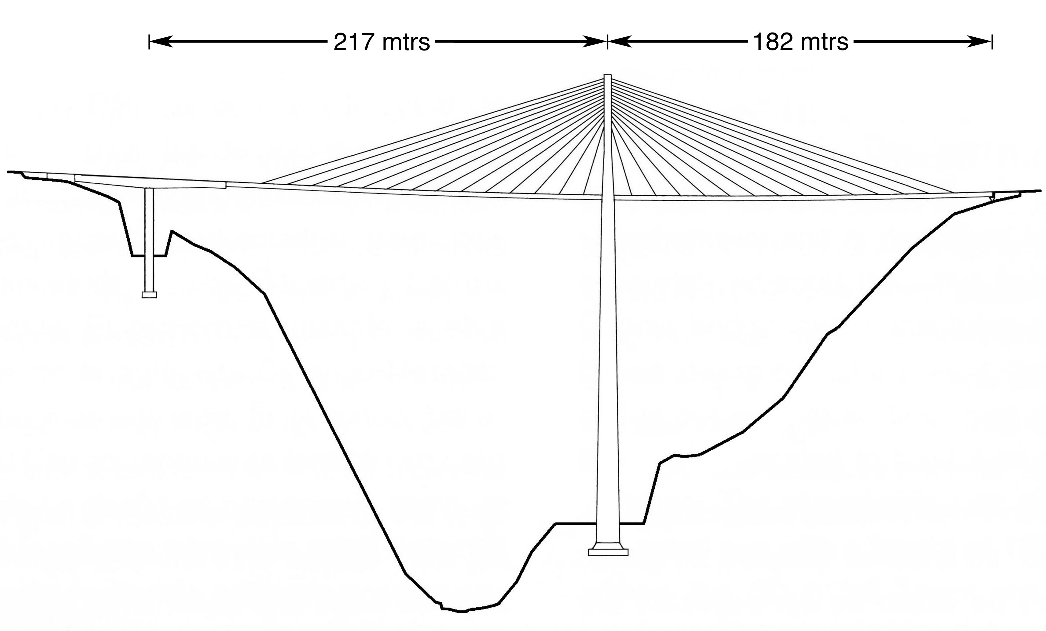
Puente El Carrizo drawing by Eric Sakowski / HighestBridges.com
El Carrizo fue diseñado originalmente como un puente viga de dos claros en voladizo, antes de ser rediseñado como un puente atirantado de un sólo mástil. El diseño actual tiene un vano central de 30 segmentos, cada uno con longitudes individuales de 8 metros y uno central de 12 metros donde la cubierta pasa a través de la torre. 28 de estos segmentos están conectados al mástil central por pares de tirantes.
El Carrizo was originally designed as a two span cantilevered beam bridge before it was redesigned as a single tower cable stayed bridge. The current design has a central span of 30 segments, each with individual lengths of 8 meters and a central unit of 12 meters where the deck passes through the tower. 28 of these segments are connected to the central mast by a pair of stays. Image by Eric Sakowski / HighestBridges.com
Image by Eric Sakowski / HighestBridges.com
Los puentes más altos de México y la Torre Mayor
Más altos puentes de México y Torre Mayor diagram by Eric Sakowski / HighestBridges.com and Skyscraperpage.com
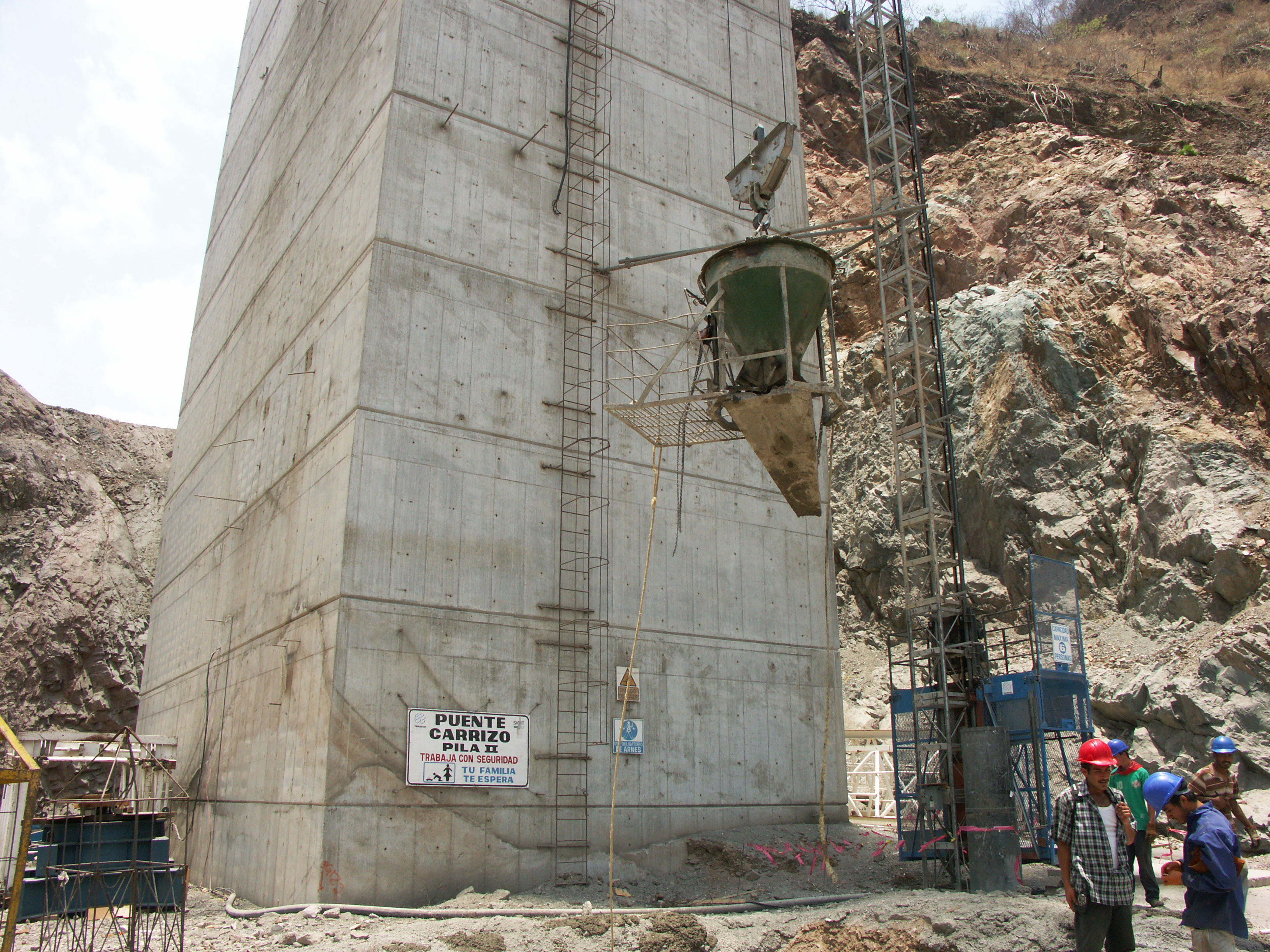
Pila II del puente El Carrizo. Image by Eric Sakowski / HighestBridges.com
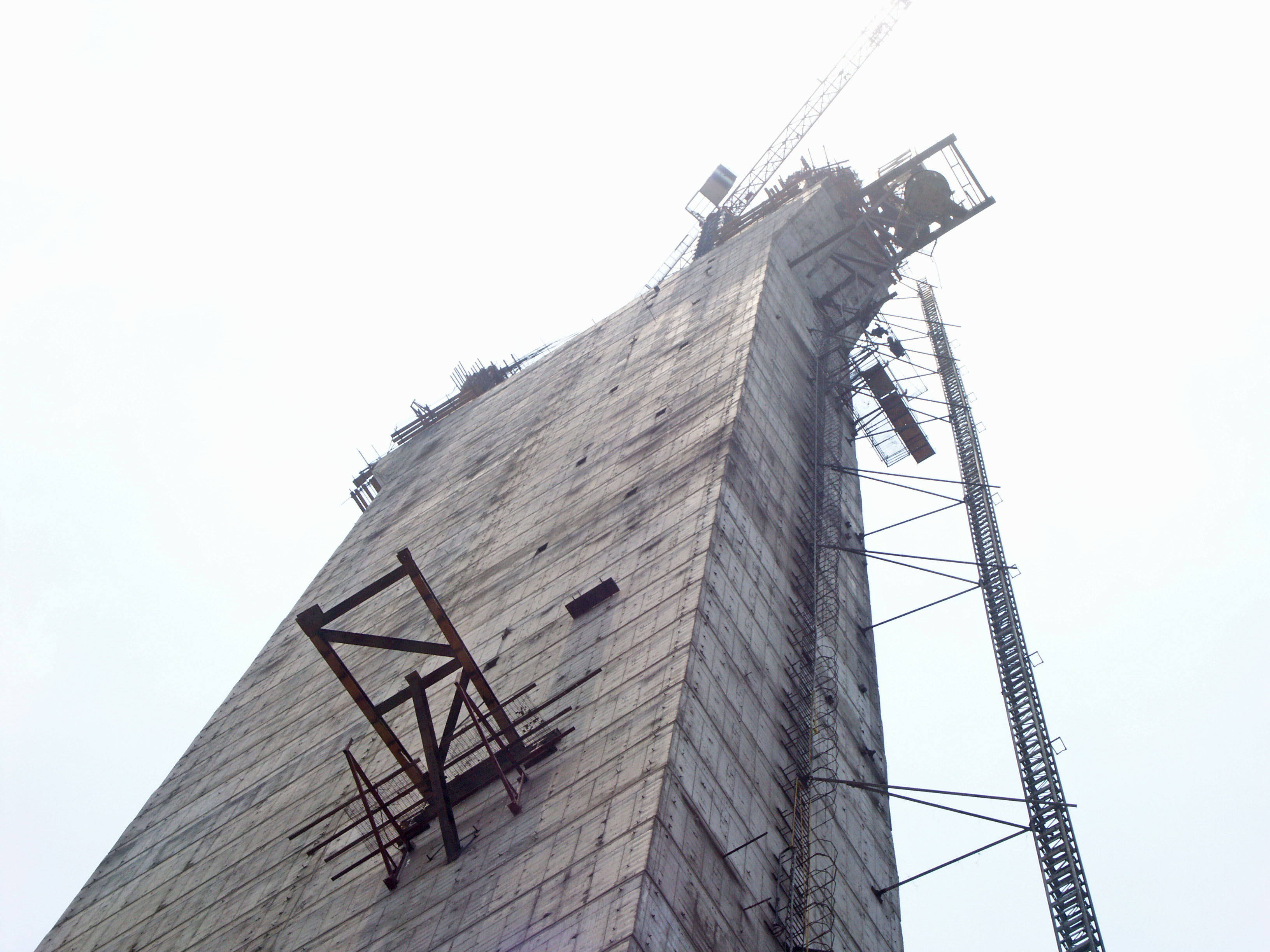
Image by Eric Sakowski / HighestBridges.com
Image by Eric Sakowski / HighestBridges.com
¡11 trabajadores cuelgan 200 metros por encima del cañón El Carrizo!
11 workers hang 200 meters above the canyon of El Carrizo! Image by Eric Sakowski / HighestBridges.com
Imagen satelital del Puente El Carrizo.
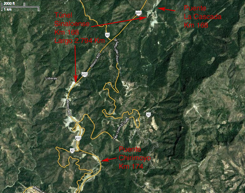
Puentes en los kilómetros 167 - 175 y el túnel Sinaloense
.
Puente La Cascada en el kilómetro 168. El puente cuenta con 7 claros: uno de 37.5, 5 de 50 y uno de 37.5 metros. Image by Eric Sakowski / HighestBridges.com
Imagen satelital del Puente Cascada.
Túnel Sinaloenese -
¡El túnel más grande en la carretera Durango-Mazatlán!
Image by SCT
Portal del túnel Sinaloense. Image by SCT
Portal del túnel Sinaloense. Image by SCT
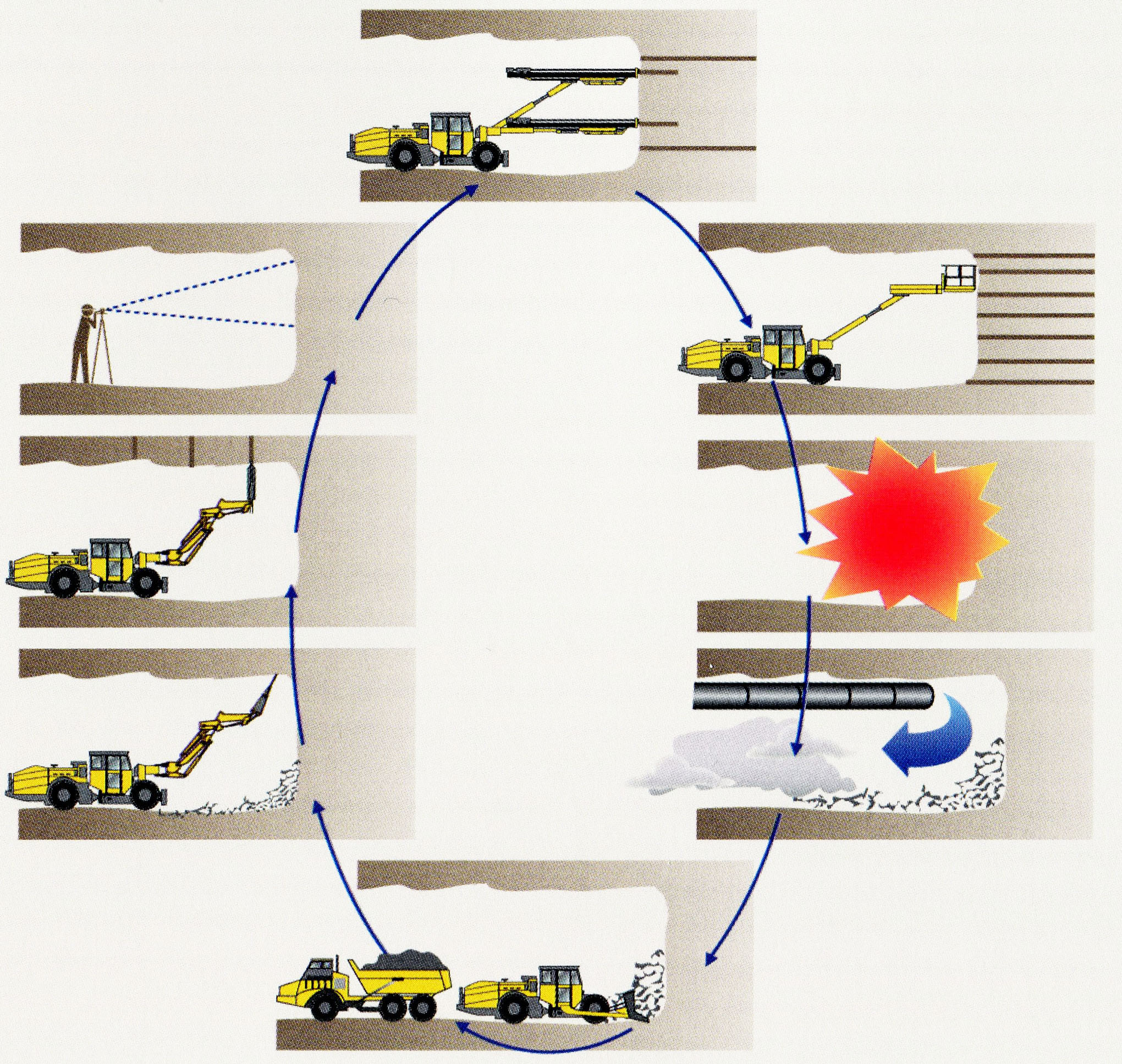
El efecto túnel básico.. Image by SCT
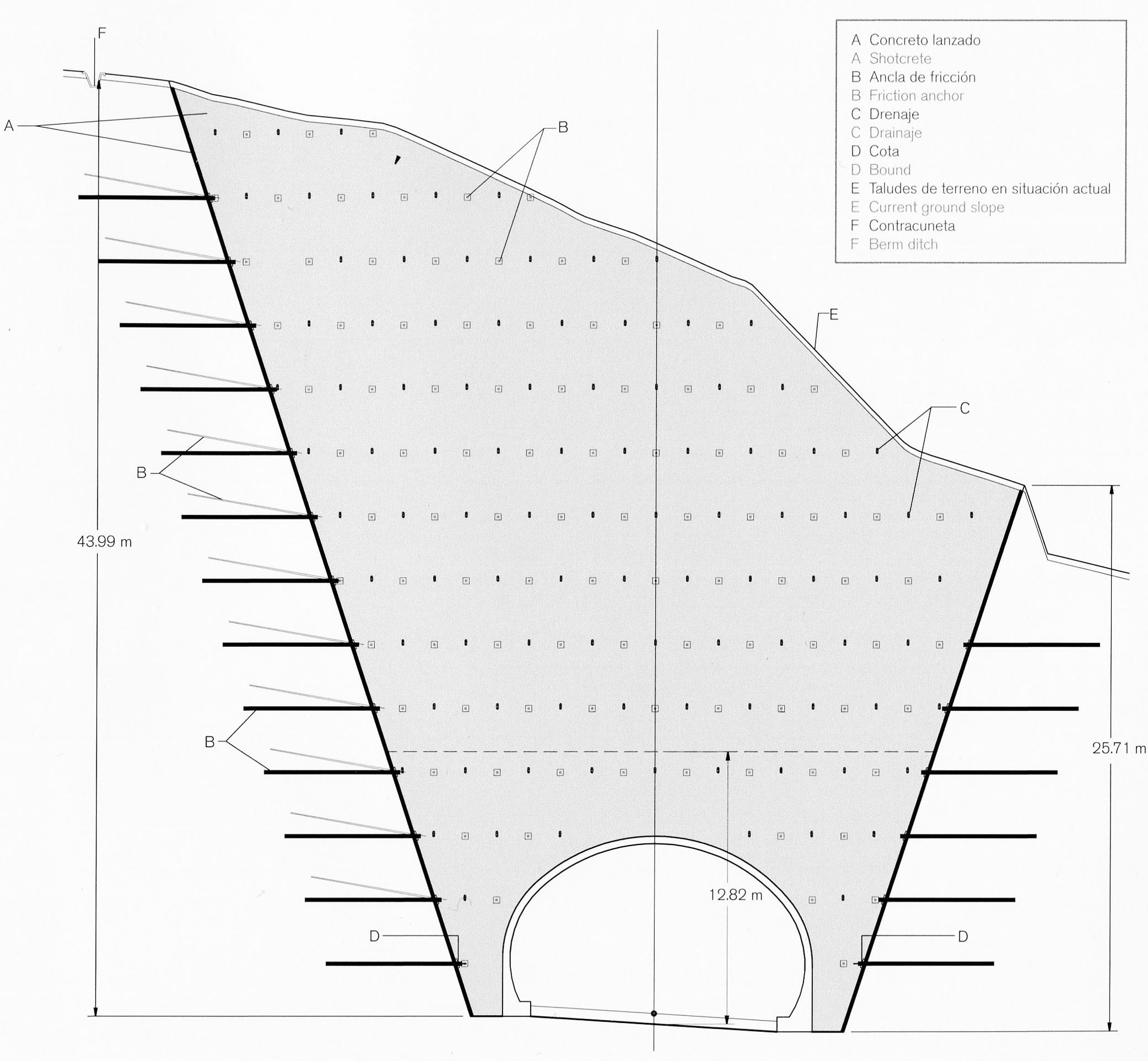
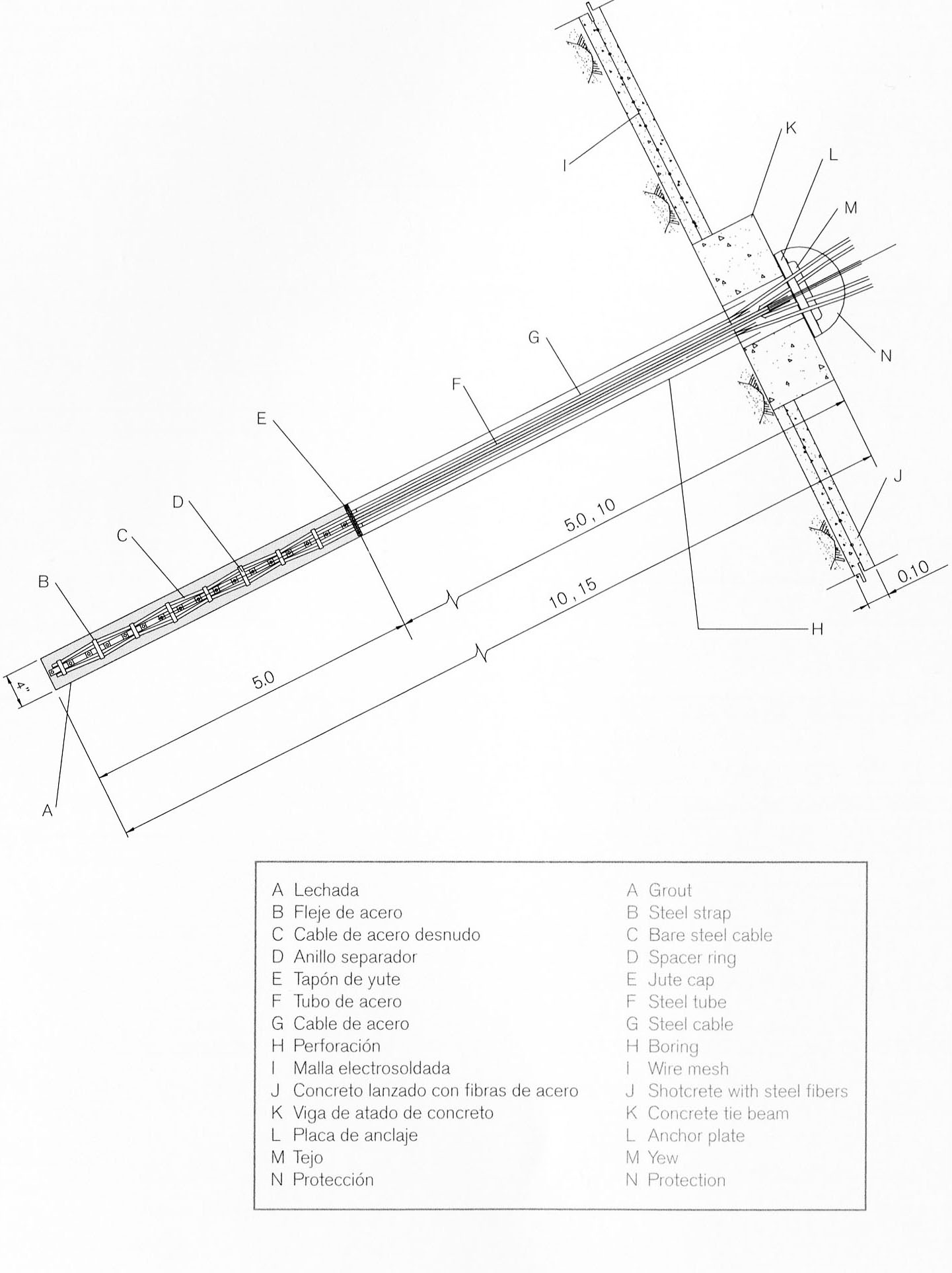
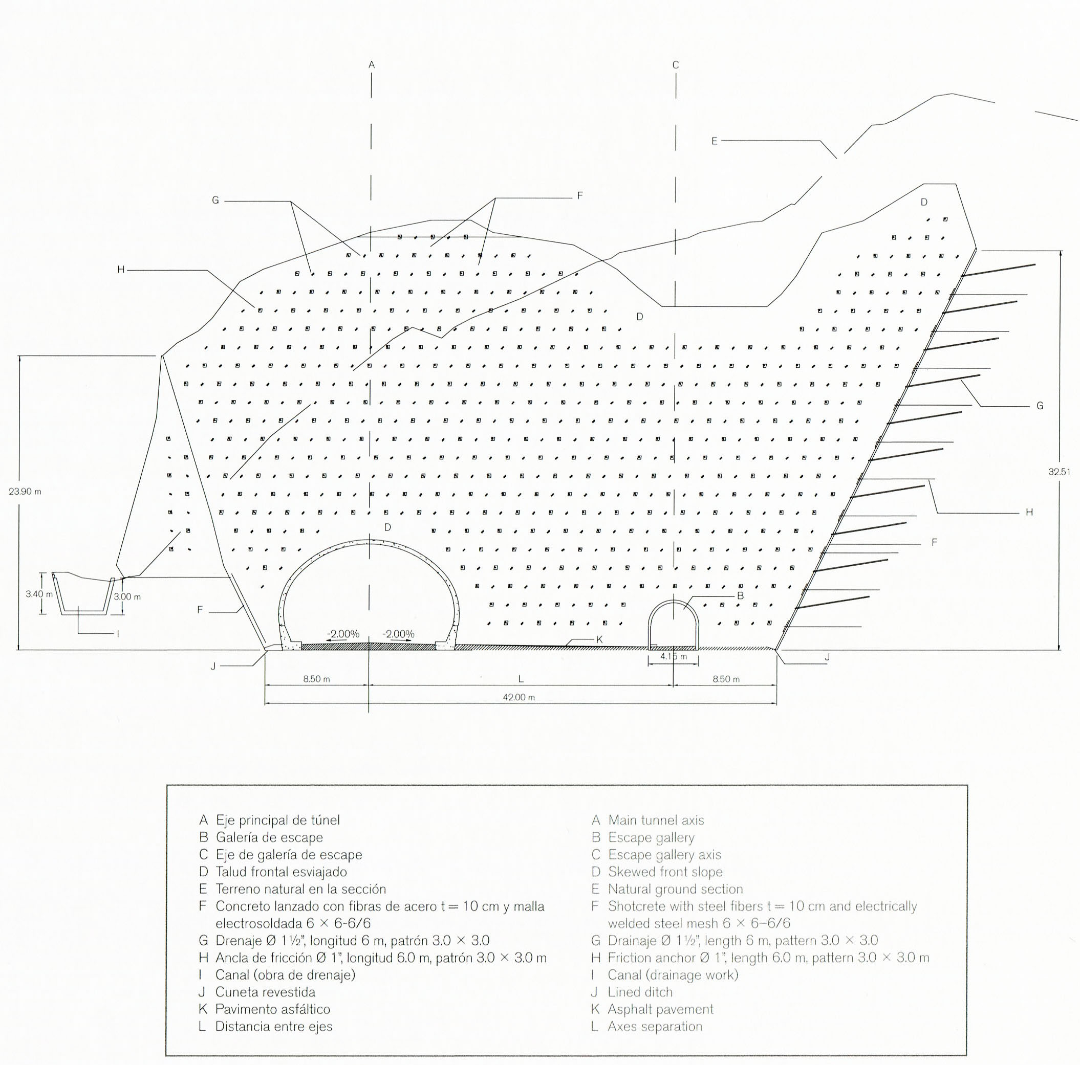
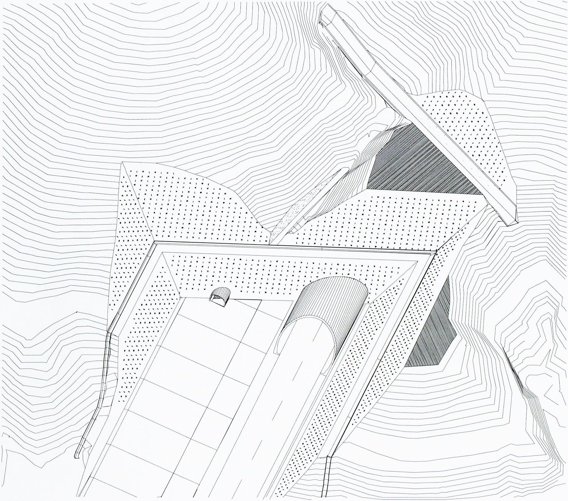
Las entradas del túnel pueden ser un punto problemático para la estabilidad de la roca, requiriendo el uso de anclas. Estos anclajes de fricción y tensión sostienen vigas de concreto que detienen masas rocosas de baja calidad.
The tunnel entrances can be a problem spot for rock stability requiring the use of anchors. These friction and tension anchors hold concrete tie beams that can hold back poor quality rock masses. Image by SCT
Image by SCT
Image by SCT
Image by SCT
La excavación del túnel se inicia en su mitad superior. Sólo después de que los soportes del techo han sido instalados, la mitad inferior del túnel puede ser excavada.
Tunnel excavation starts with the top half of the tunnel. After the roof supports are installed the bottom half of the tunnel is then dug out. Image by SCT
Image by SCT
Image by SCT
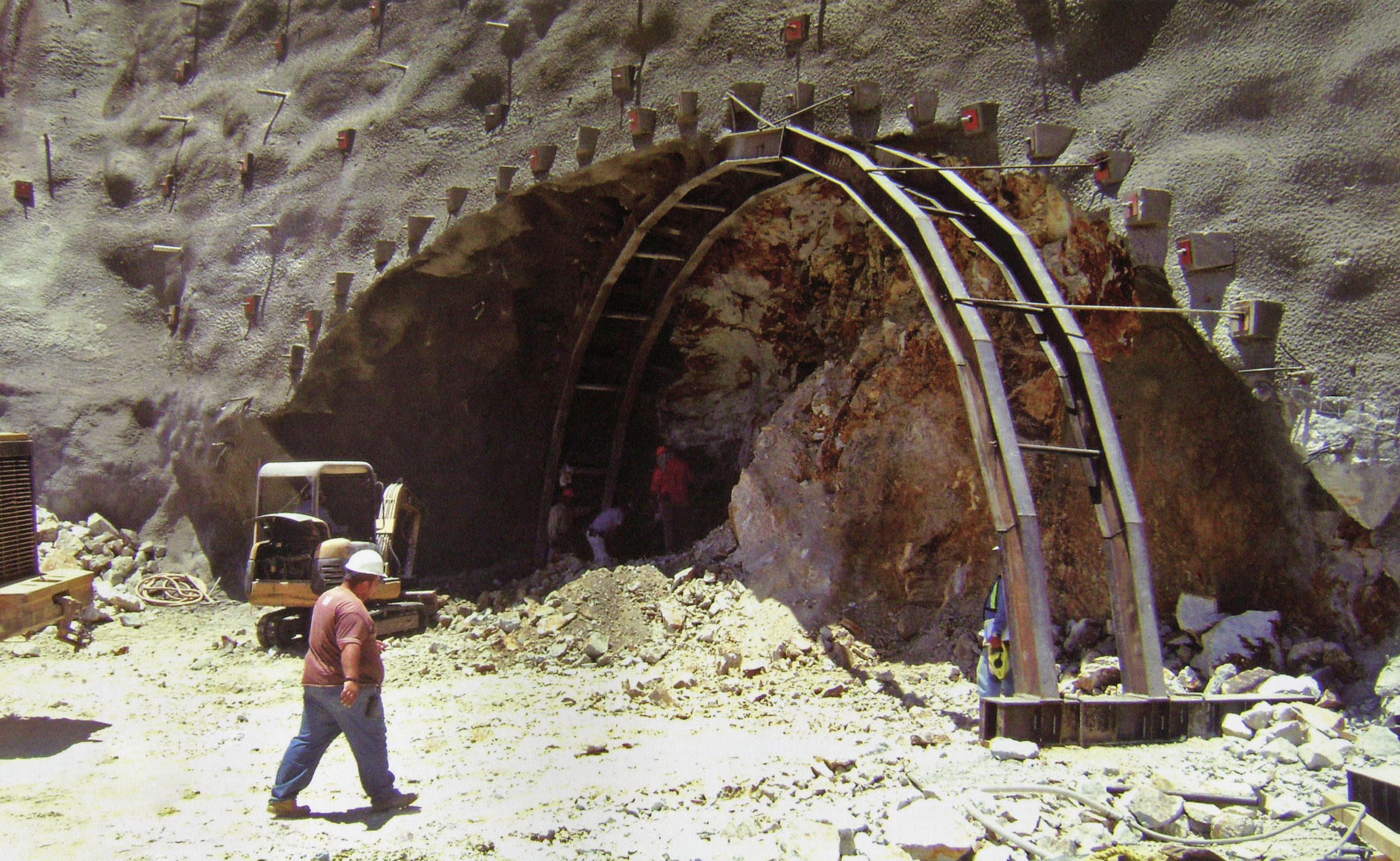
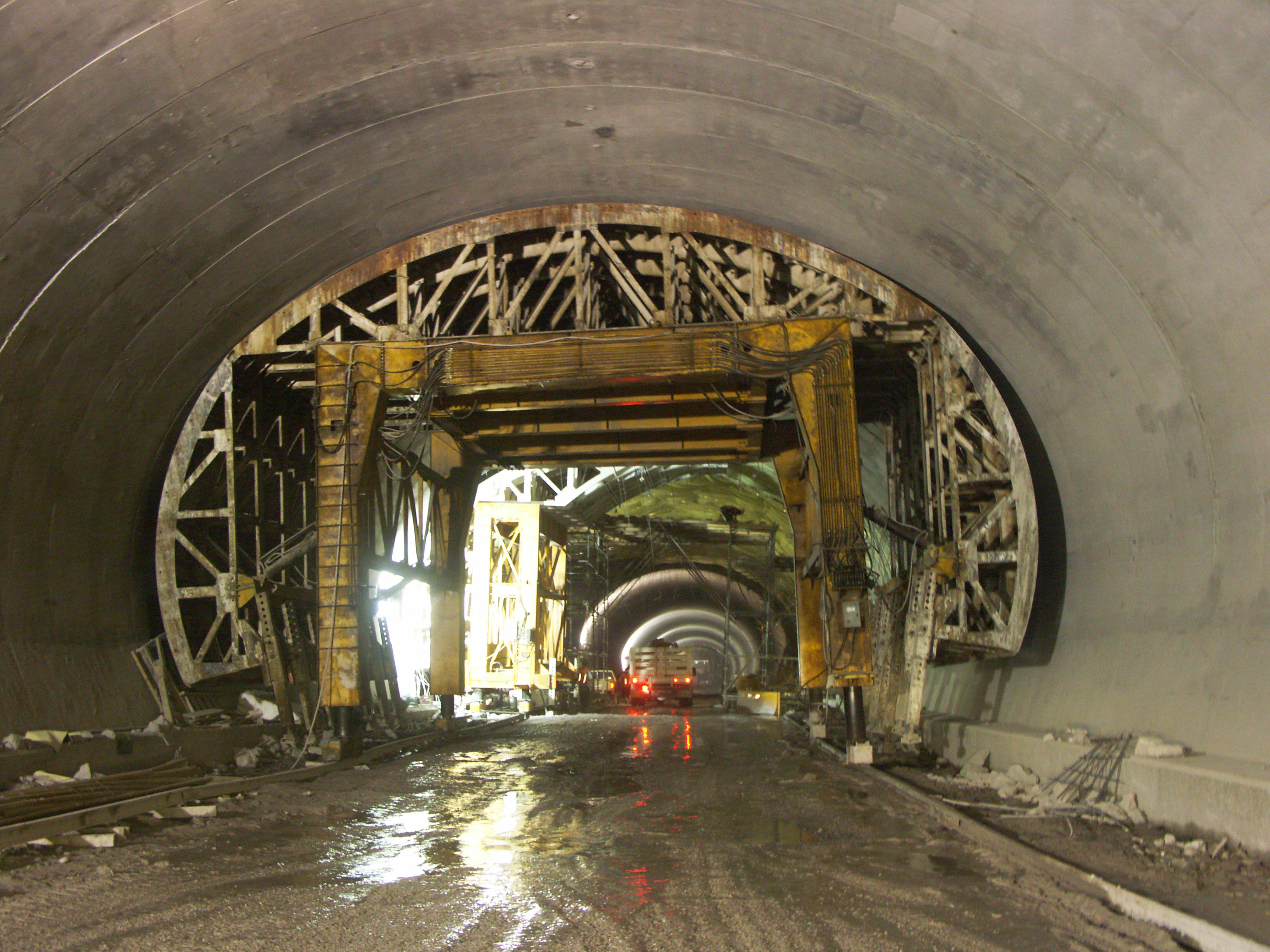
En algunas secciones del túnel, se usan maderos entre el soporte de acero y la roca provisionalmente, antes rellenar el hueco con concreto.
For some sections of tunnel, timber is used between the steel support and the rock before concrete fills in the gap. Image by SCT
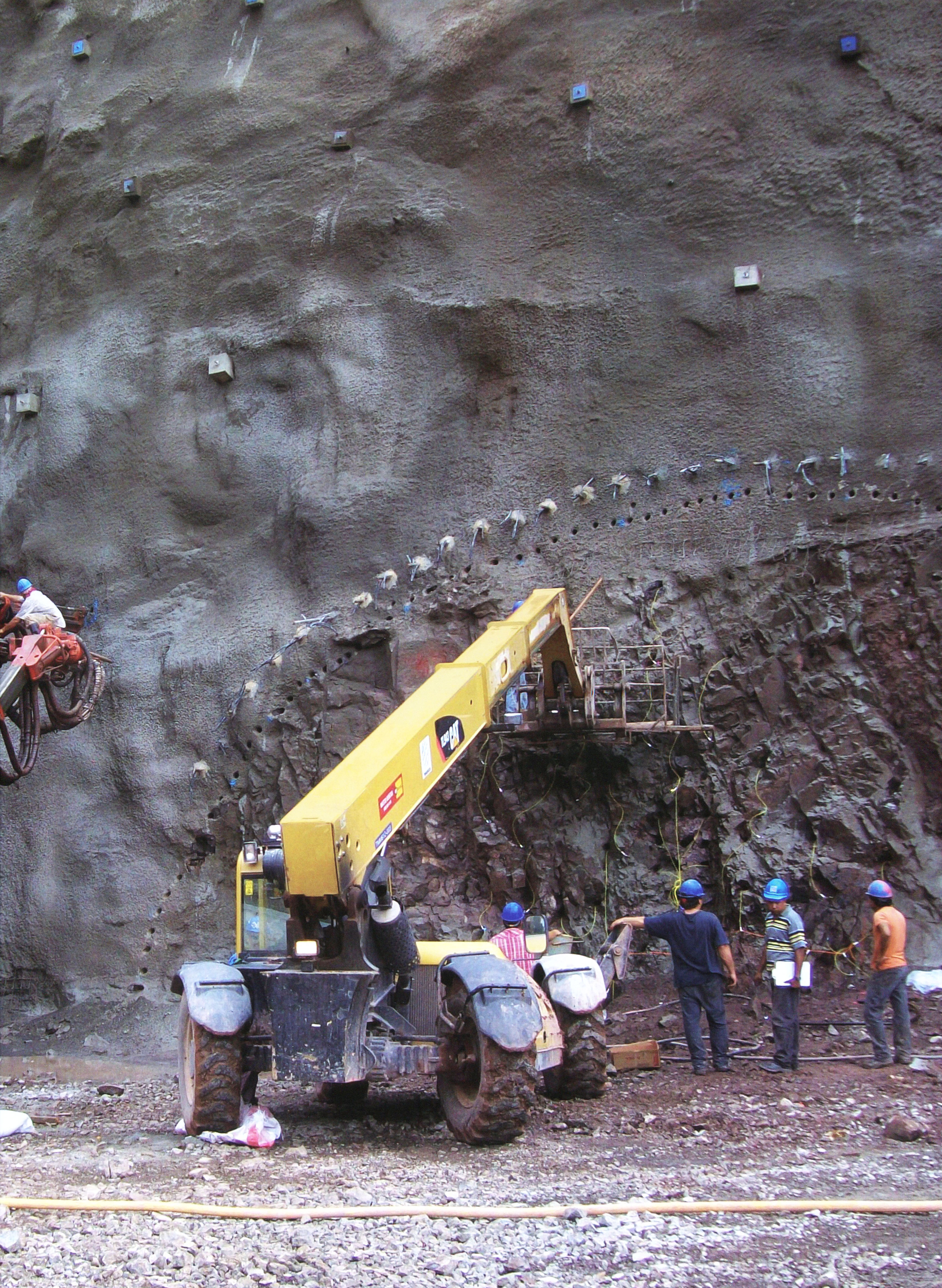
Los anclajes de fricción se usan para estabilizar la roca encima de ciertas secciones de túnel.
Friction anchors are used to stabilize the rock above certain sections of tunnel. Image by SCT
En la vista de arriba del túnel Sinaloense se puede ver el uso de anclajes de fricción en una sección y de soportes de acero en otra. El uso de varios tipos de soporte de túnel basado en el tipo de roca se desarrolló en Austria.
In the above view of the Sinaloenese tunnel you can see the use of friction anchors on one section and steel supports on another. This use of several types of tunnel supports based on the rock type was developed in Austria. Image by SCT
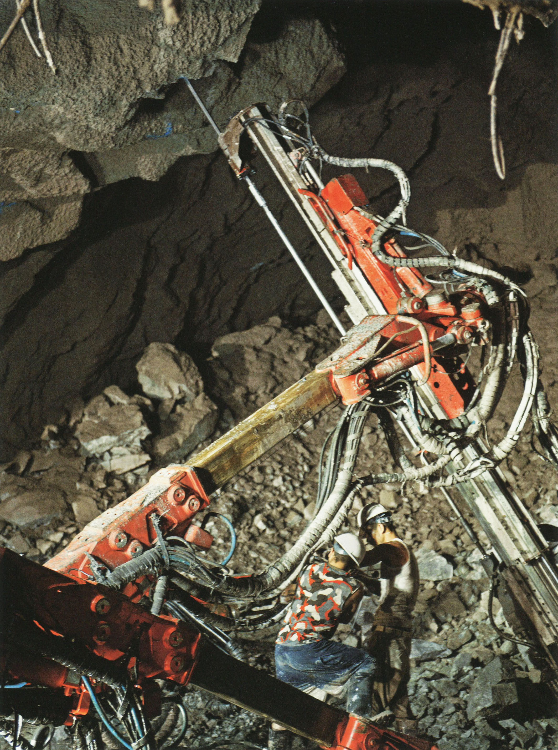
Un taladro especial se utiliza para cavar agujeros para los anclajes de fricción.
A special drill is used to dig holes for the friction anchors. Image by SCT
Los encofrados utilizados para el revestimiento final de concreto del túnel deben ajustarse a las alturas cambiantes, así como a curvas que deben ser suaves y consistentes en toda la longitud del túnel. Se fabricaron un total de 12 encofrados de acero. Tres fueron compatibles para la construcción de los túneles de 4 carriles, mientras que nueve se utilizaron para el resto de los túneles de 2 carriles.
Formworks used for the final concrete tunnel lining must adjust to changing heights as well as curves that must be smooth and consistent for the entire length of the tunnel. There were a total of 12 steel formworks made. Three were compatible for the construction of the 4-lane tunnels while nine were used for the rest of the 2-lane tunnels. Image by Eric Sakowski / HighestBridges.com
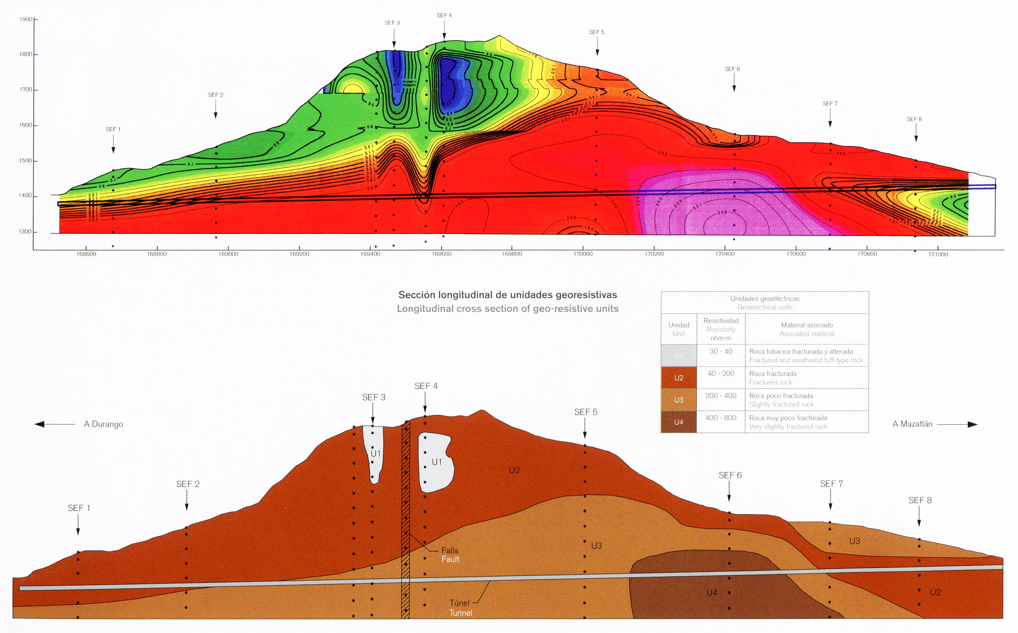
Para el estudio de la roca muy por debajo del recorrido del túnel Sinaloense, se adoptaron sondeos electromagnéticos de frecuencia, aplicando el método magneto-telúrico de fuente controlada. Además, se aplicó un sistema de refracción sísmica, detectando vibraciones de 12 diferentes geófonos que leen las ondas sísmicas generadas en la tierra. Diez diferentes perforaciones también se realizaron para determinar la calidad de la roca a diferentes profundidades.
To study the rock deep below the path of the Sinaloense tunnel, Electromagnetic Frequency Soundings were adopted applying the Controlled Source Audio Magneto Telluric method. In addition, a seismic refraction system was applied, detecting vibrations from 12 different geophones that read the seismic waves generated into the ground. Ten different borings were also made to determine rock quality at different depths. Image by SCT
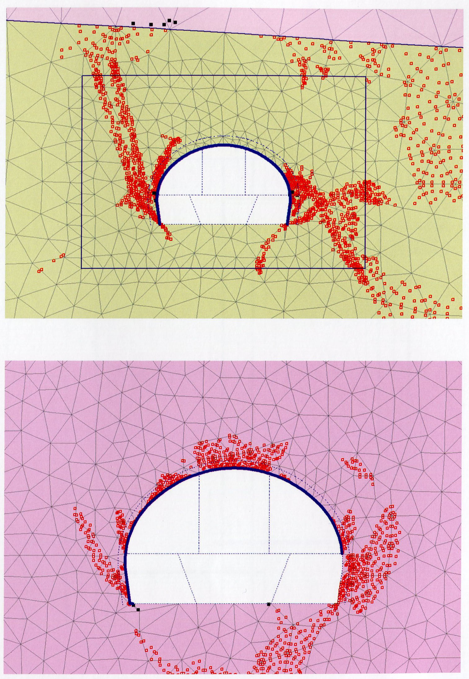
Diagramas de tensión para dos diferentes secciones del túnel Sinaloense.
Stress diagrams for two different sections of the Sinaloense tunnel. Image by SCT
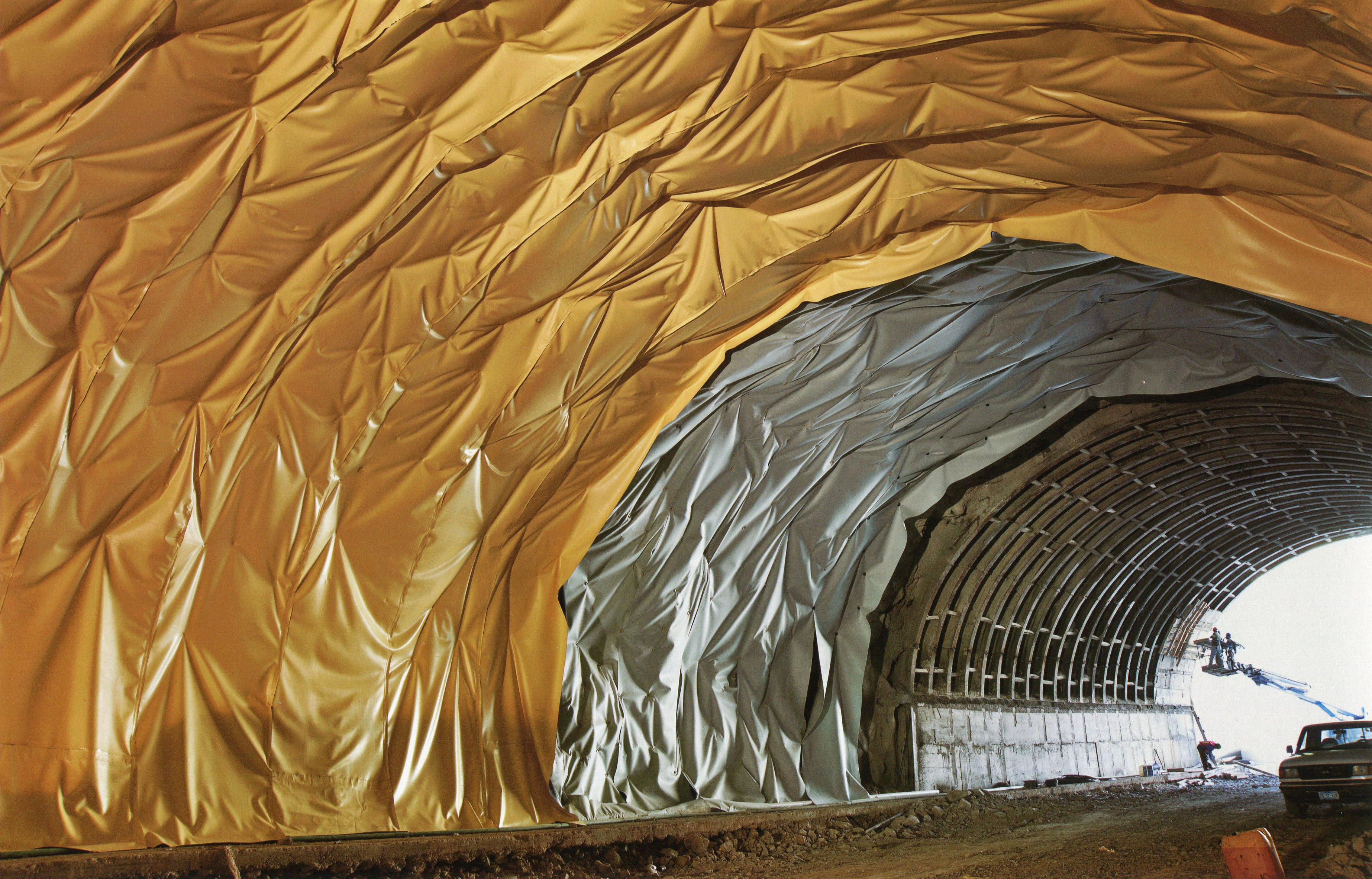
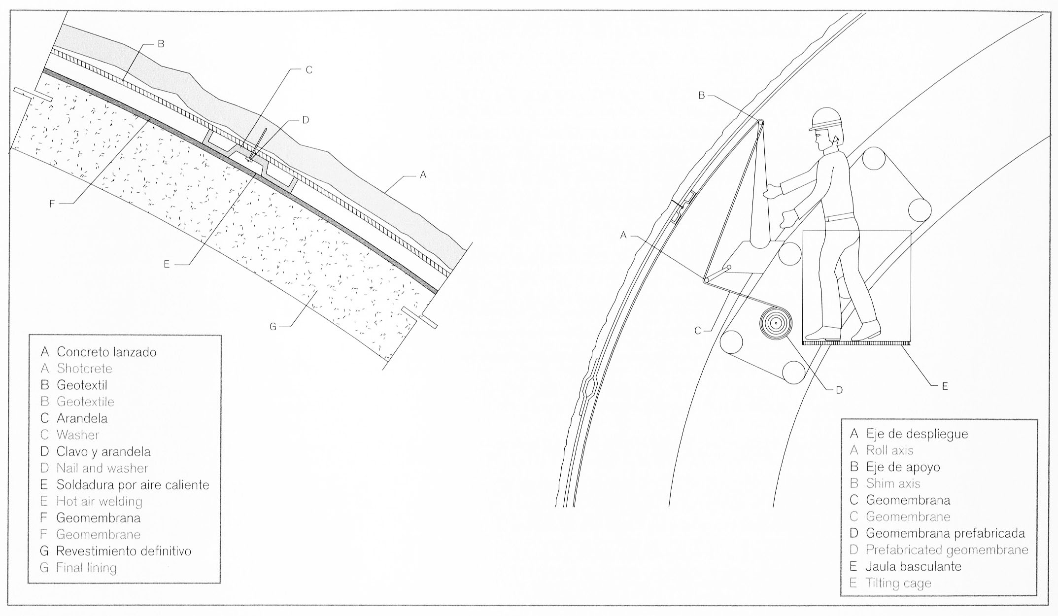
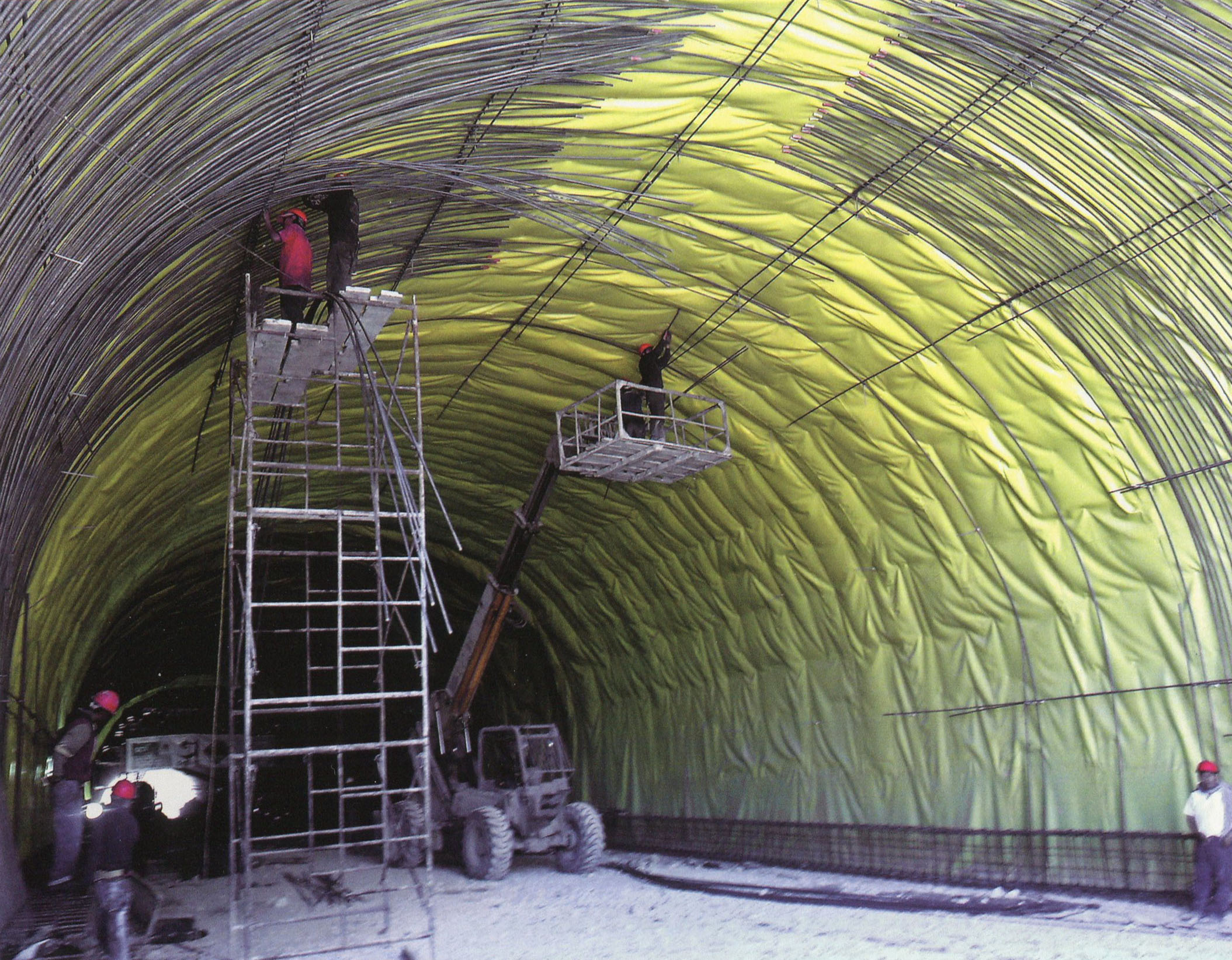
La última capa del revestimiento de un túnel consta de una membrana conocida como geotextil, una tela no tejida de fibra de poliéster. Esta membrana recoge las filtraciones de agua de la roca y las transmite al drenaje en la parte inferior del túnel.
The final layer of tunnel lining consists of a membrane known as geotextile, a non-woven polyester fiber fabric. This membrane collects water seepage from the rock and conveys it to the drainage works at the bottom of the tunnel. Image by SCT
Image by SCT
Image by SCT
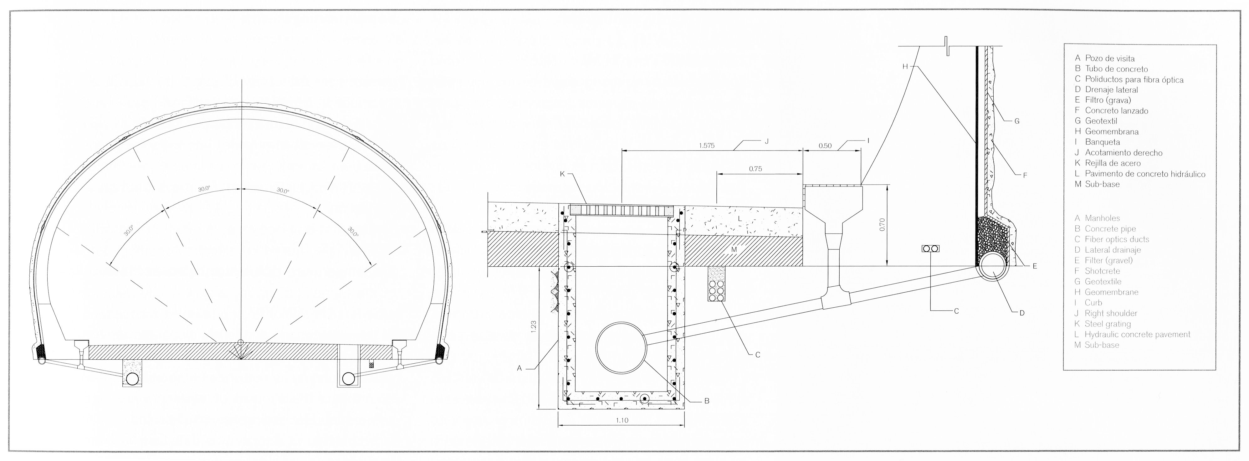
Diagrama del drenaje de agua en la parte inferior del túnel.
Diagram of water drainage at the bottom of the tunnel. Image by SCT
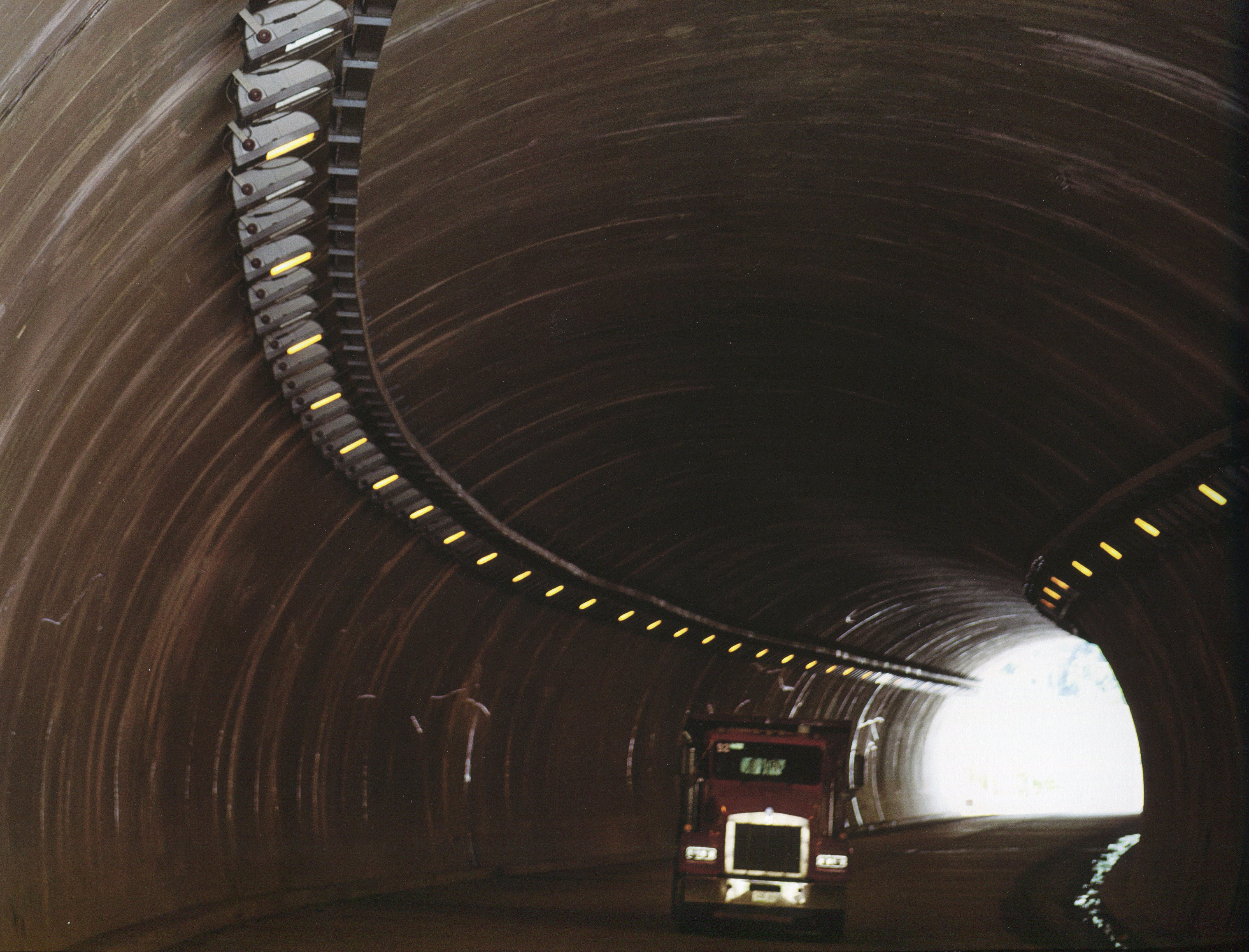
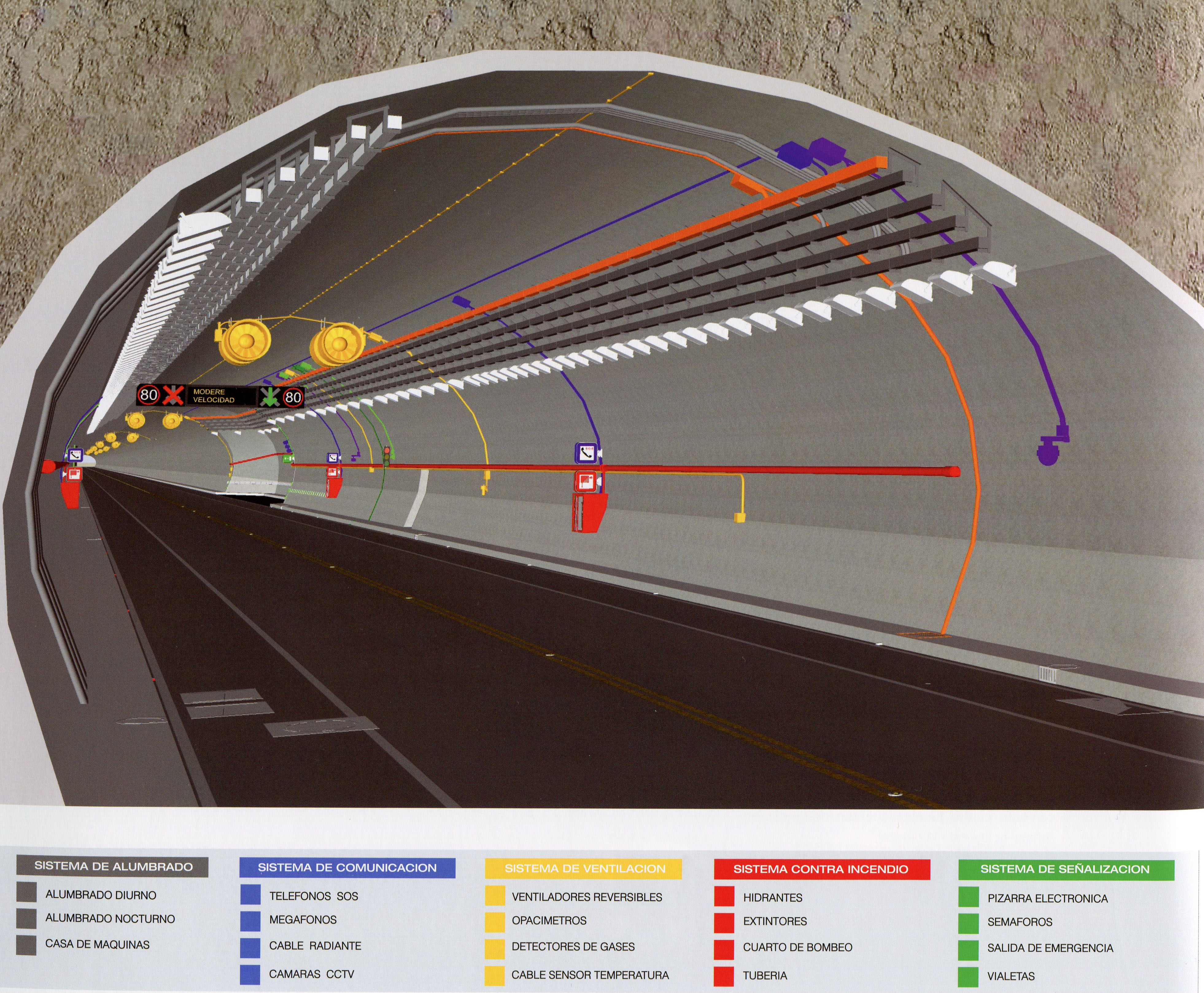
Dado que los túneles son mucho más oscuros que la luz exterior, las lámparas se ajustan en 5 zonas que permiten al ojo humano adaptarse y ajustarse a la menor cantidad de luz en el interior del túnel sin ceguera momentánea.
Since tunnels are much darker then the outside light, the lamps are adjusted into 5 zones that allow the human eye to adapt and adjust to the lower luminance inside the tunnel without momentary blindness. Image by SCT
Los nueve túneles más largos, de más de 400 metros de longitud, se consideran túneles "inteligentes". Cuentan con sistemas de fibra óptica que permiten el monitoreo y la comunicación continua, incluyendo sensores que leen los niveles de CO y NO2, así como cámaras y altavoces para cualquier situación de emergencia que pueda surgir. El centro de datos y control se encuentra en el km 172.
The nine longest tunnels over 400 meters in length are considered “intelligent” tunnels with fiber optics systems that allow monitoring and continuous communication including sensors that can read CO and NO2 levels as well as cameras and loudspeakers for any emergency situations that may arise. The central data and control center is located at km 172. Image by SCT
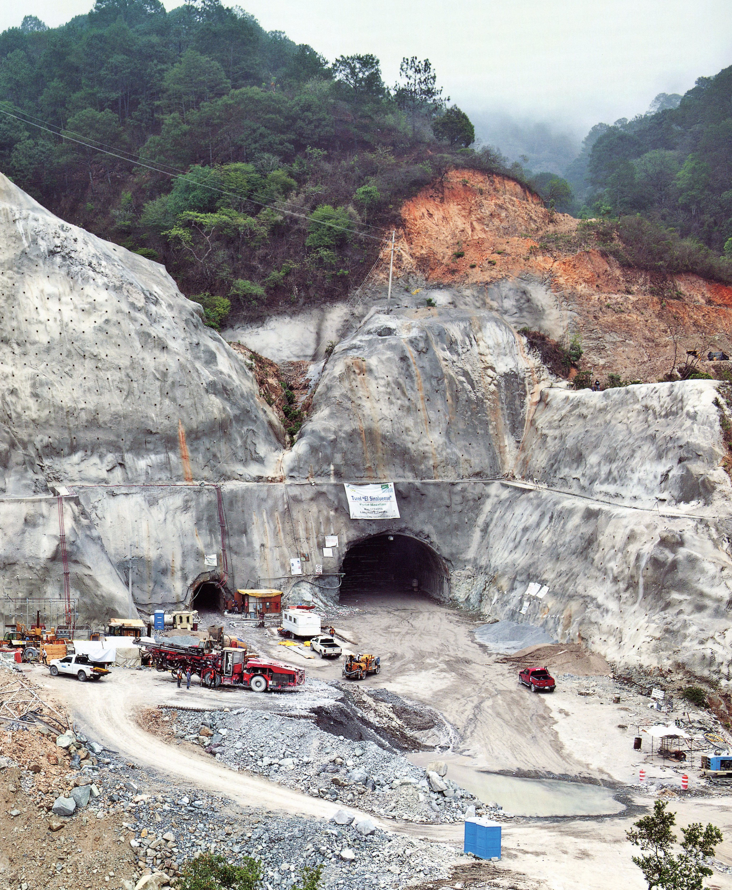
Portal poniente del túnel Sinaloenese. Image by SCT
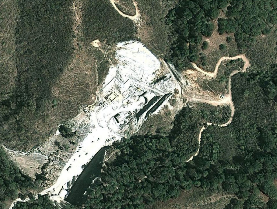
Imagen satelital del portal poniente del túnel Sinaloenese.
Portal poniente del túnel Sinaloenese. Image by SCT
Portal poniente del túnel Sinaloenese. Image by SCT
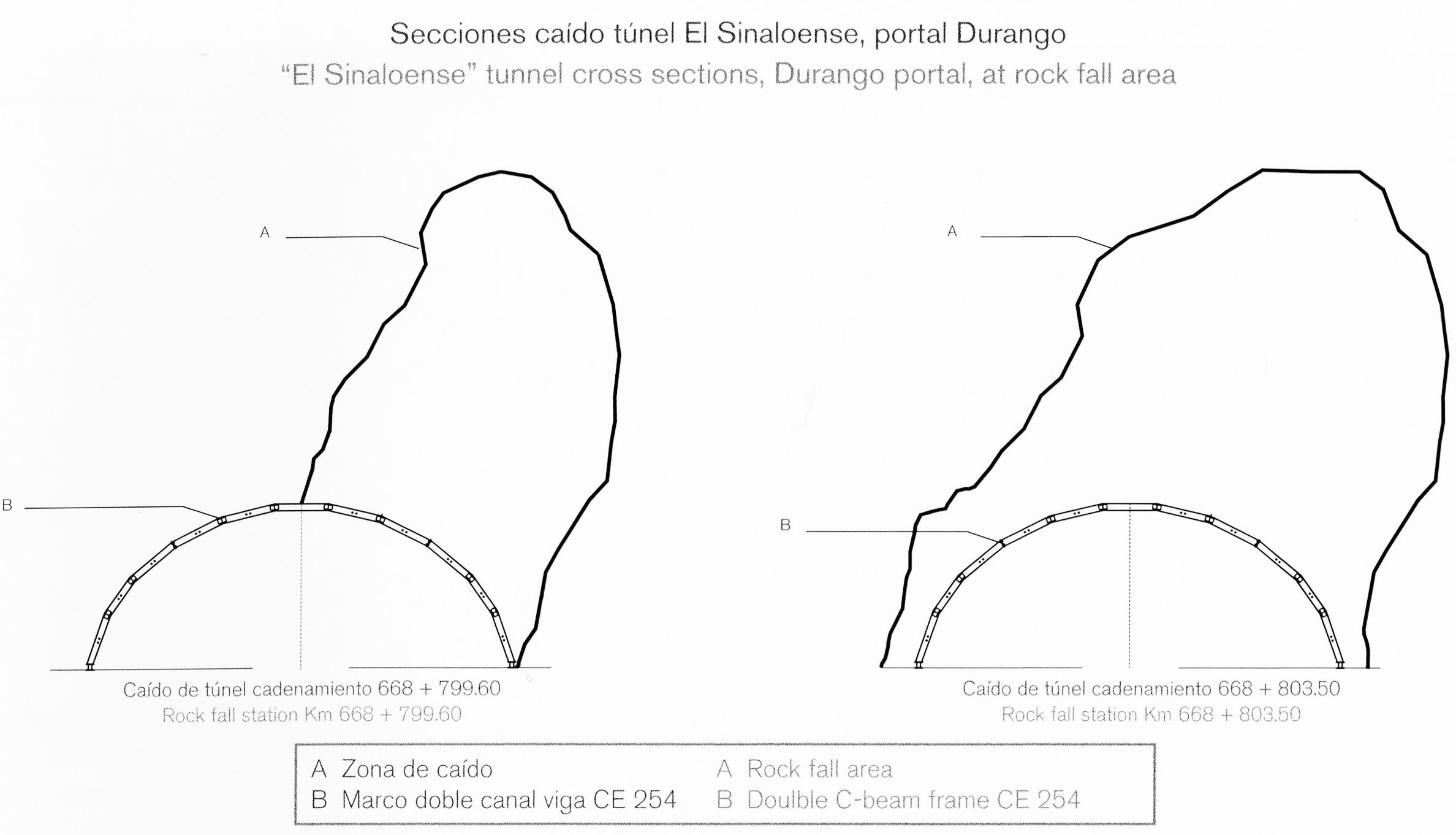
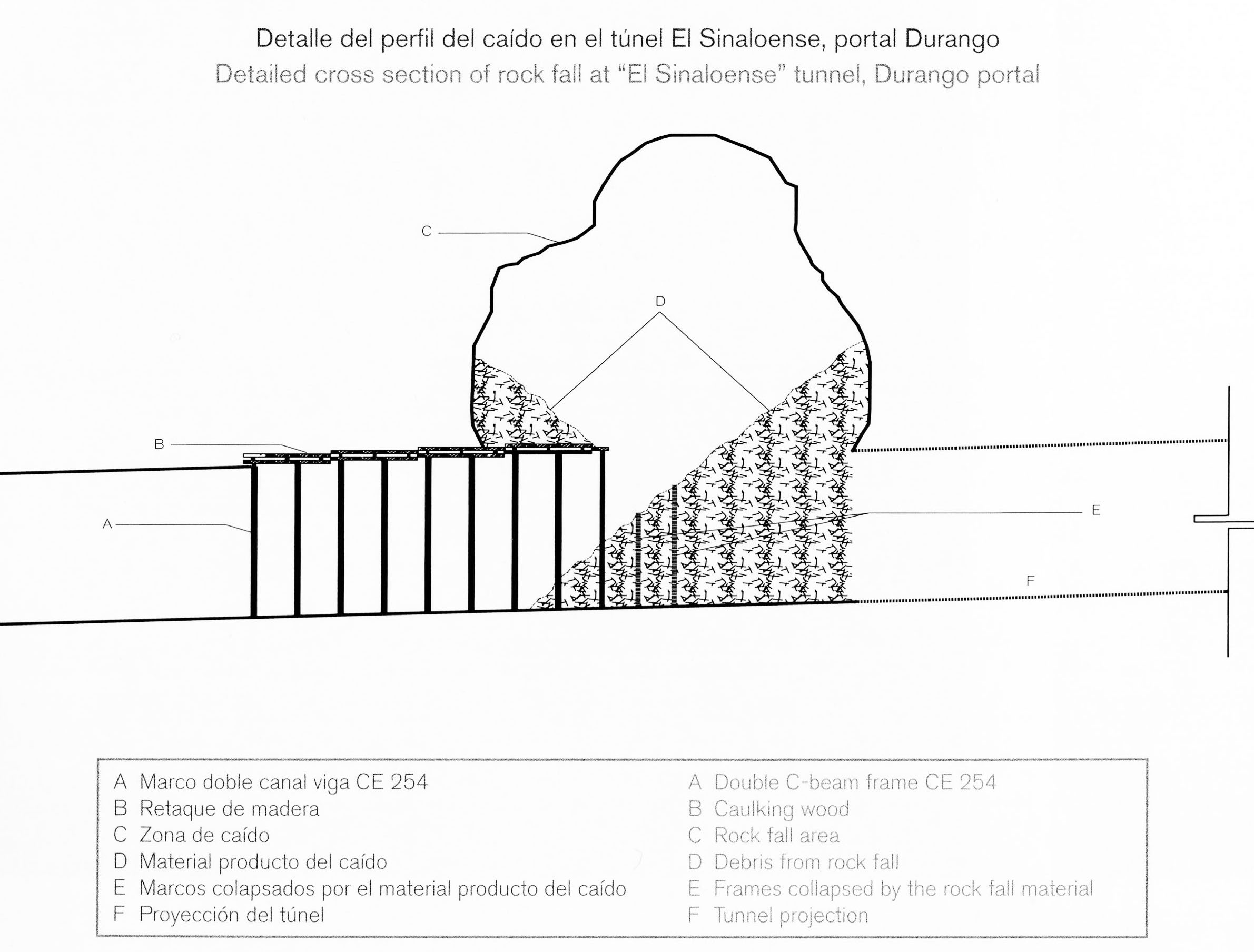
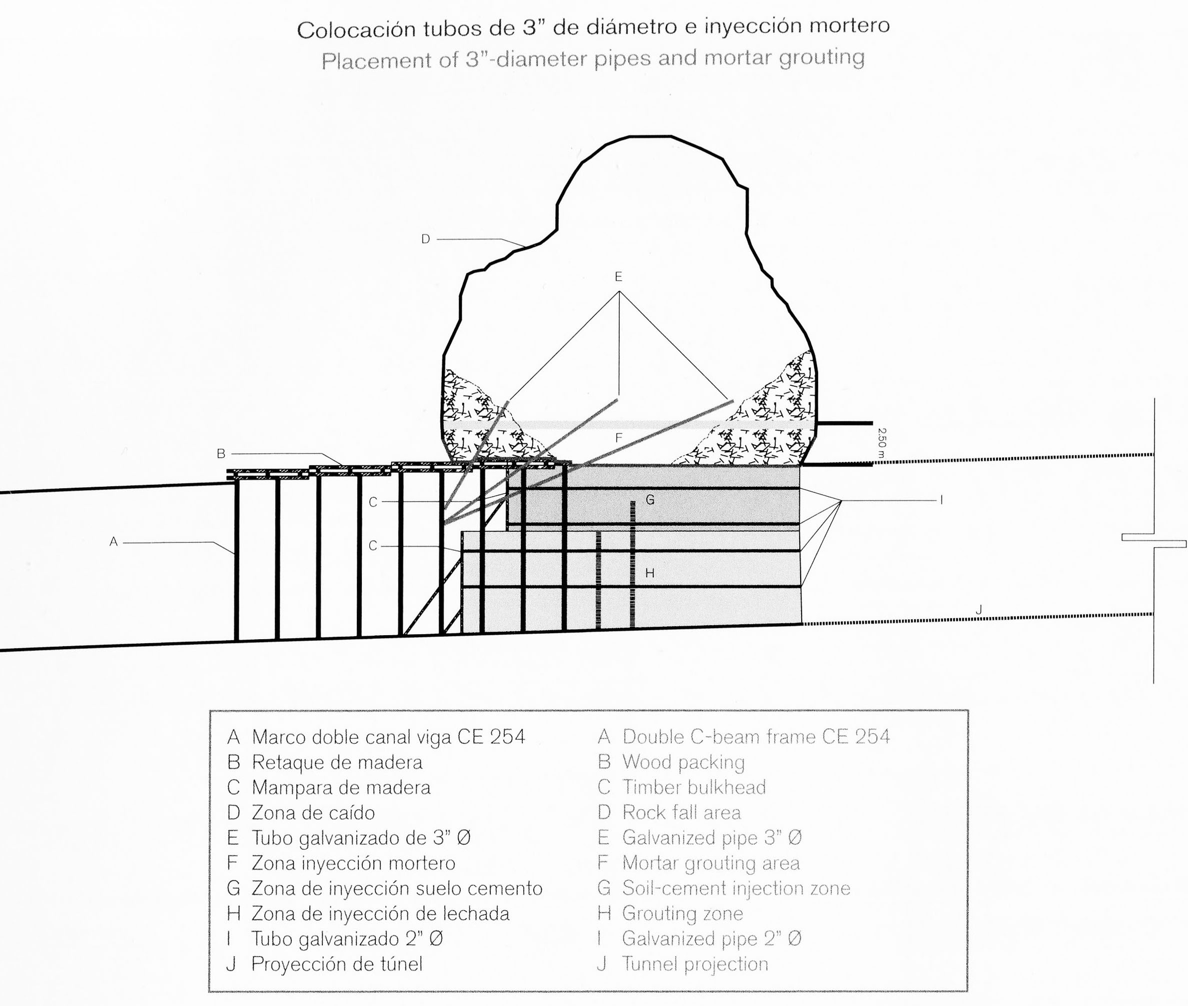
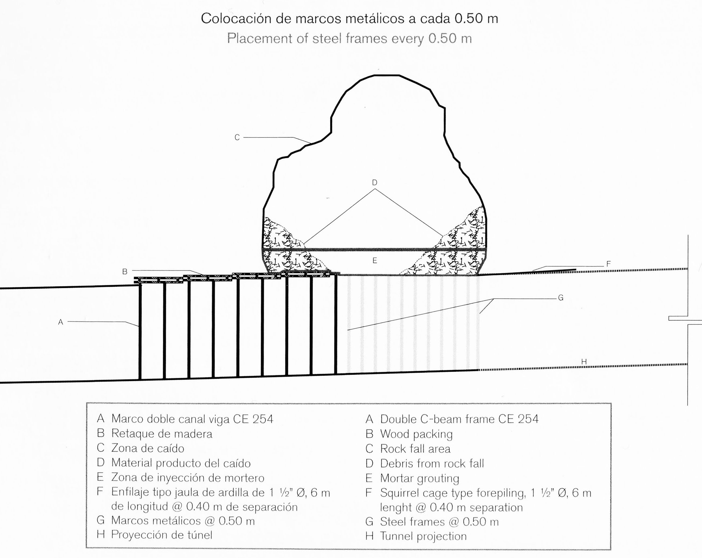
El problema más difícil en la construcción de túneles carreteros ocurrió cuando se produjo un colapso en el lado poniente del túnel Sinaloenese. Varias secciones de la estructura de soporte de acero se derrumbaron por la caída de roca.
The most difficult problem of the entire highway tunnel construction occured from a collapse along the west side of the Sinaloenese tunnel. Several sections of the steel support frame were collapsed by the rock fall. Image by SCT
Image by SCT
Image by SCT
Image by SCT
Se colocaron marcos de acero por debajo de la entrada de la cueva a intervalos de tan sólo .5 metros, además de tubo galvanizado y refuerzo de mortero.
Steel frames were placed below the cave opening at intervals of just .5 meters in addition to galvanized pipe and mortar reinforcement. Image by SCT
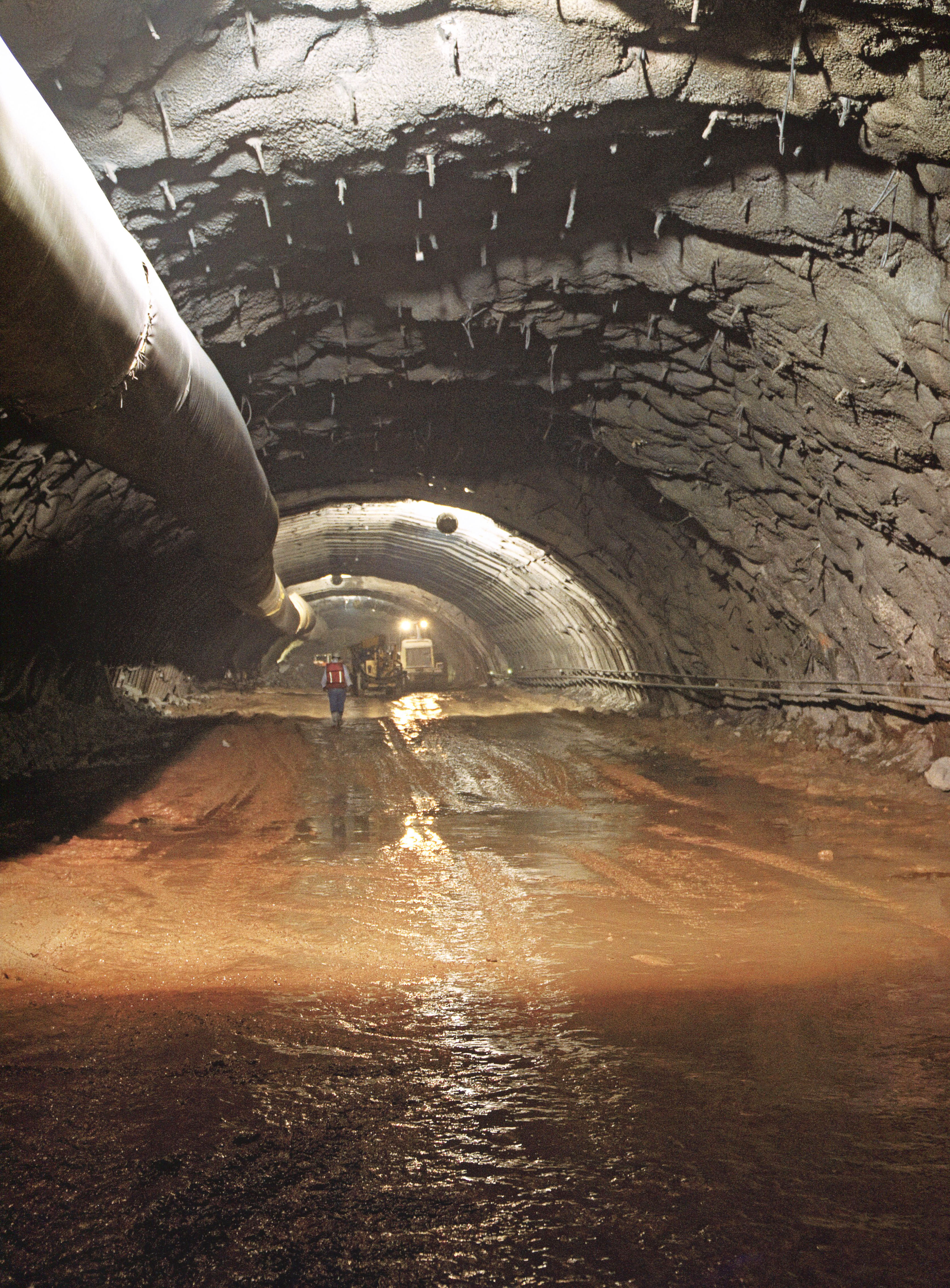
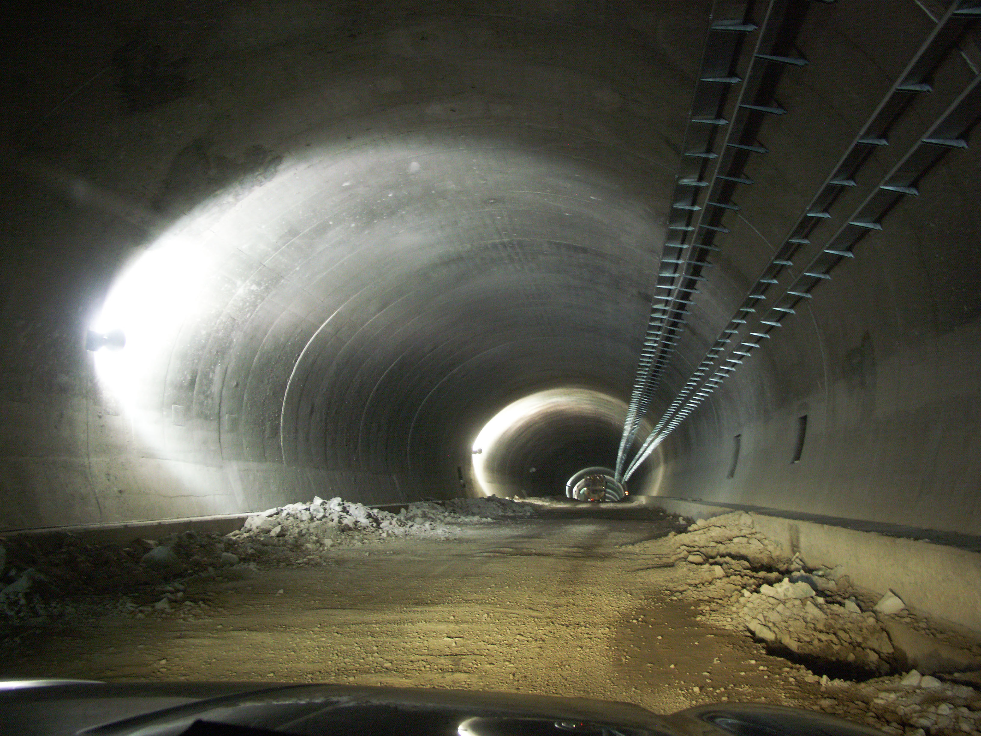
Túnel Sinaloenese. Image by Eric Sakowski / HighestBridges.com
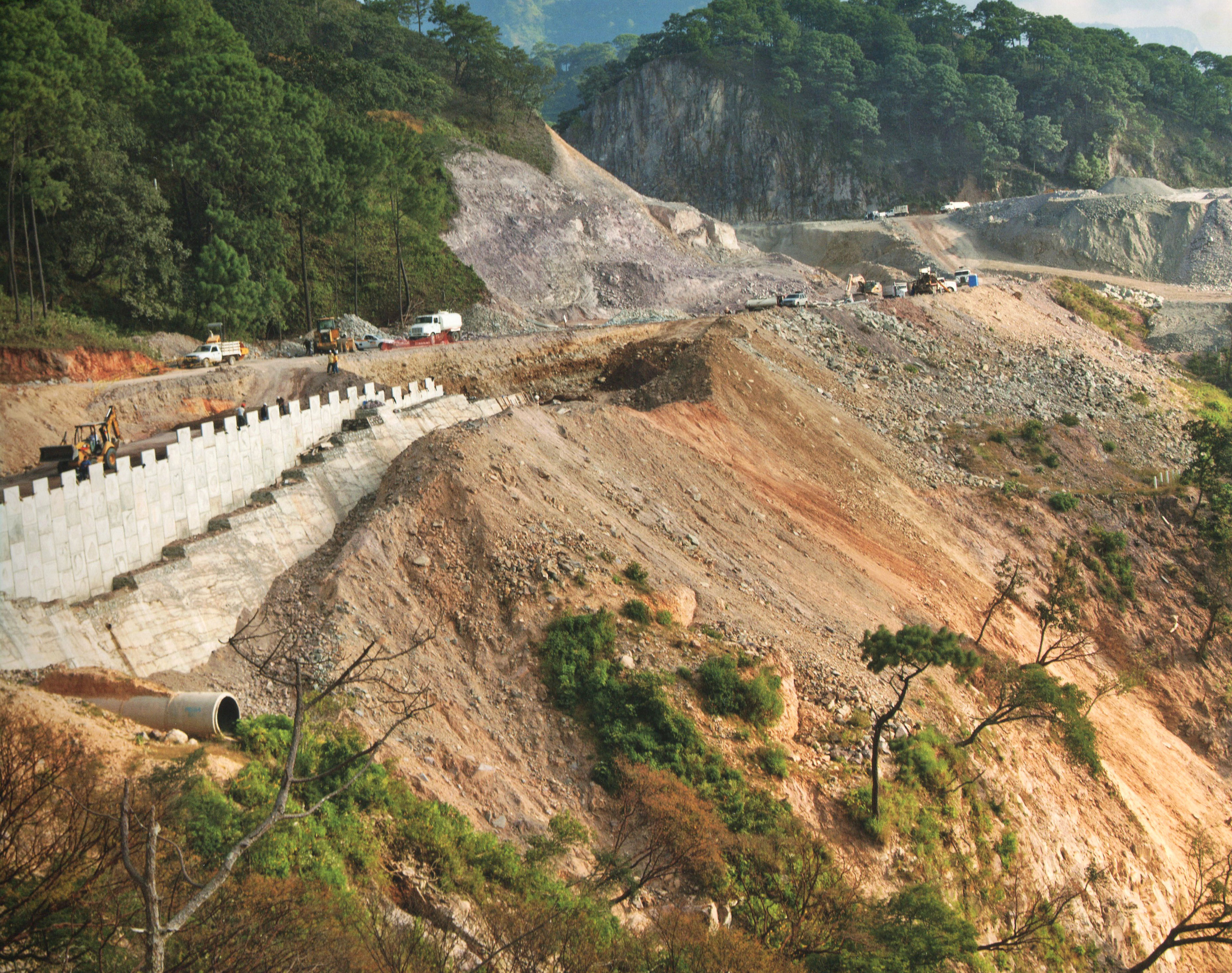
Pared y obra de drenaje en el kilómetro 172.
Wall and water culvert at kilometer 172. Image by SCT
Puente Chirimoyo y viaducto Chirimoyo en el kilómetro 174. Los dos puentes cuentan respectivamente con 5 claros: uno de 29, 3 de 38 y uno de 29 metros; y 6 claros de 30 metros. Image by Eric Sakowski / HighestBridges.com
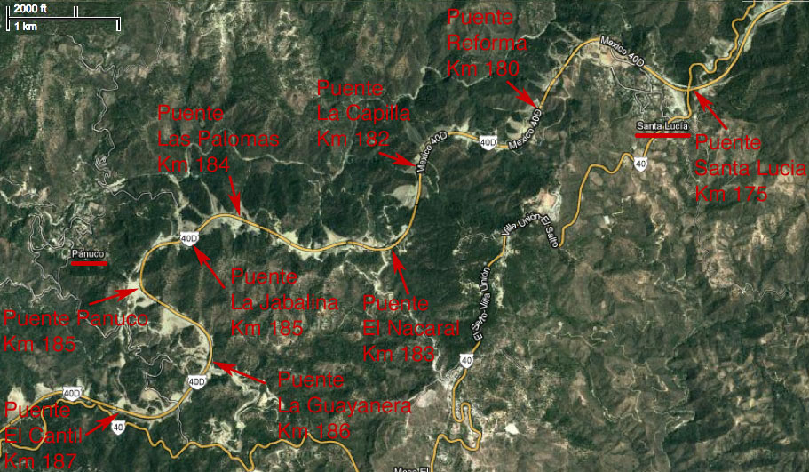
Puentes en los kilómetros 175 - 188
Puente Santa Lucía en el kilómetro 175. El puente Santa Lucía es el más grande y más alto situado al oeste del túnel Sinaloenese. El puente cuenta con 8 claros: uno de 37.5, 6 de 50 y uno de 37.5 metros. Image by Eric Sakowski / HighestBridges.com
Image by Eric Sakowski / HighestBridges.com
La carretera pasa a 95 metros de altura. Image by Eric Sakowski / HighestBridges.com
Imagen satelital del puente Santa Lucia.
Un túnel falso cerca de Santa Lucía.
A false tunnel near Santa Lucia. Image by SCT
Túnel falso cerca de Santa Lucía. Image by SCT
Túnel Santa Lucía y dos puentes pequeños.
The Santa Lucia tunnel and 2 small bridges. Image by SCT
Puente La Reforma en el kilómetro 180. El puente cuenta con 3 claros de: 37.5, 50 y 37.5 metros. Image by SCT
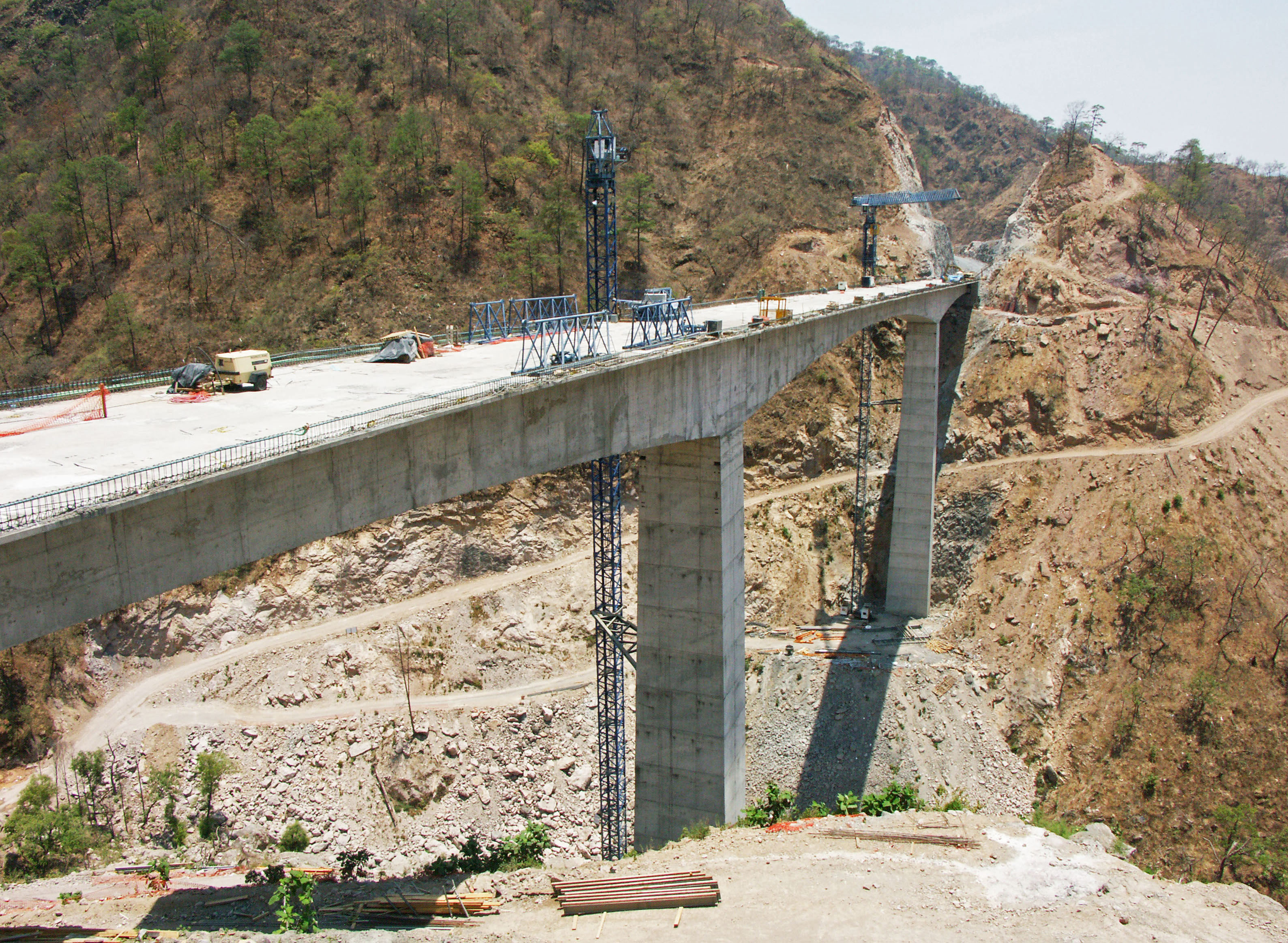
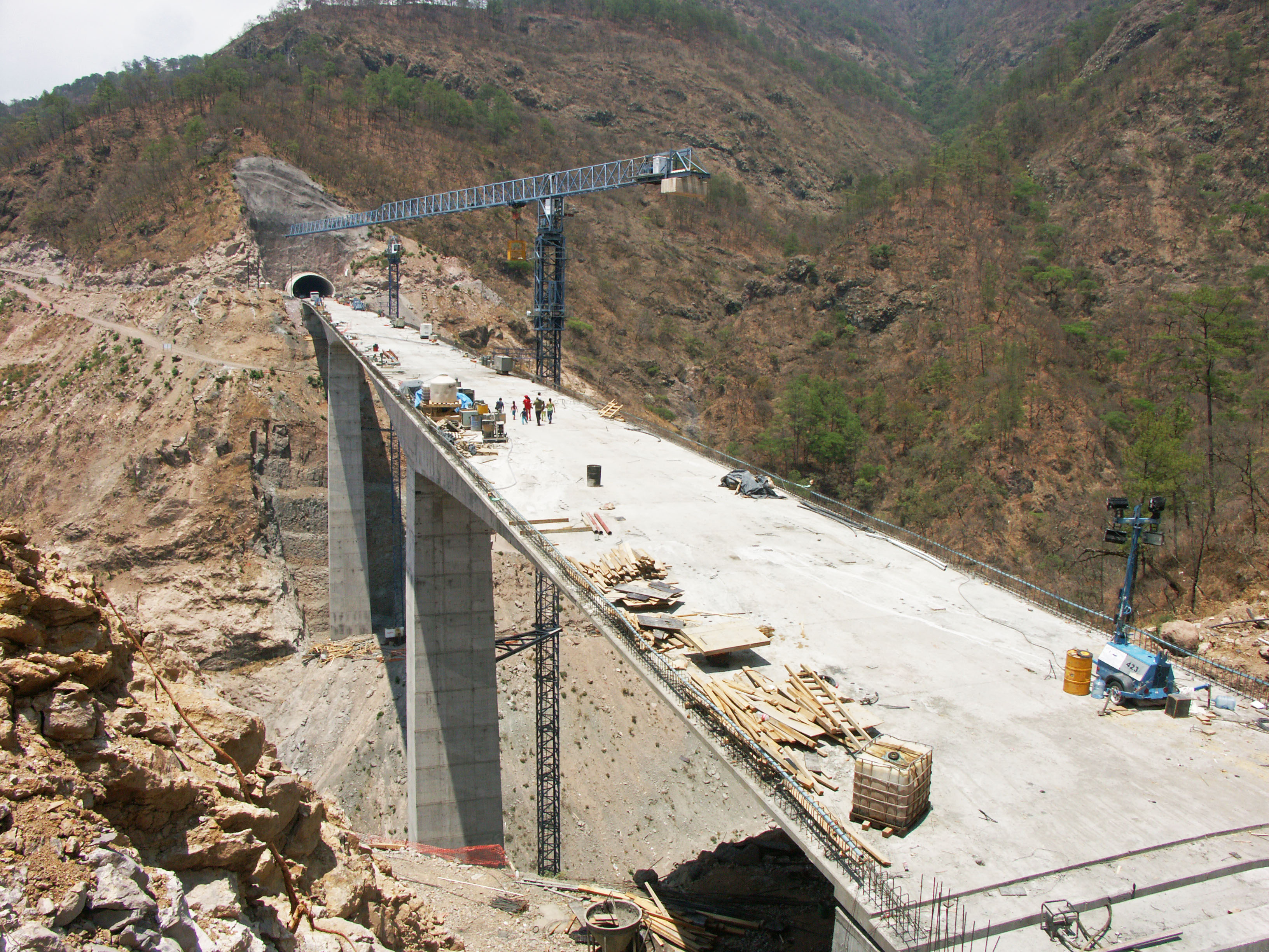
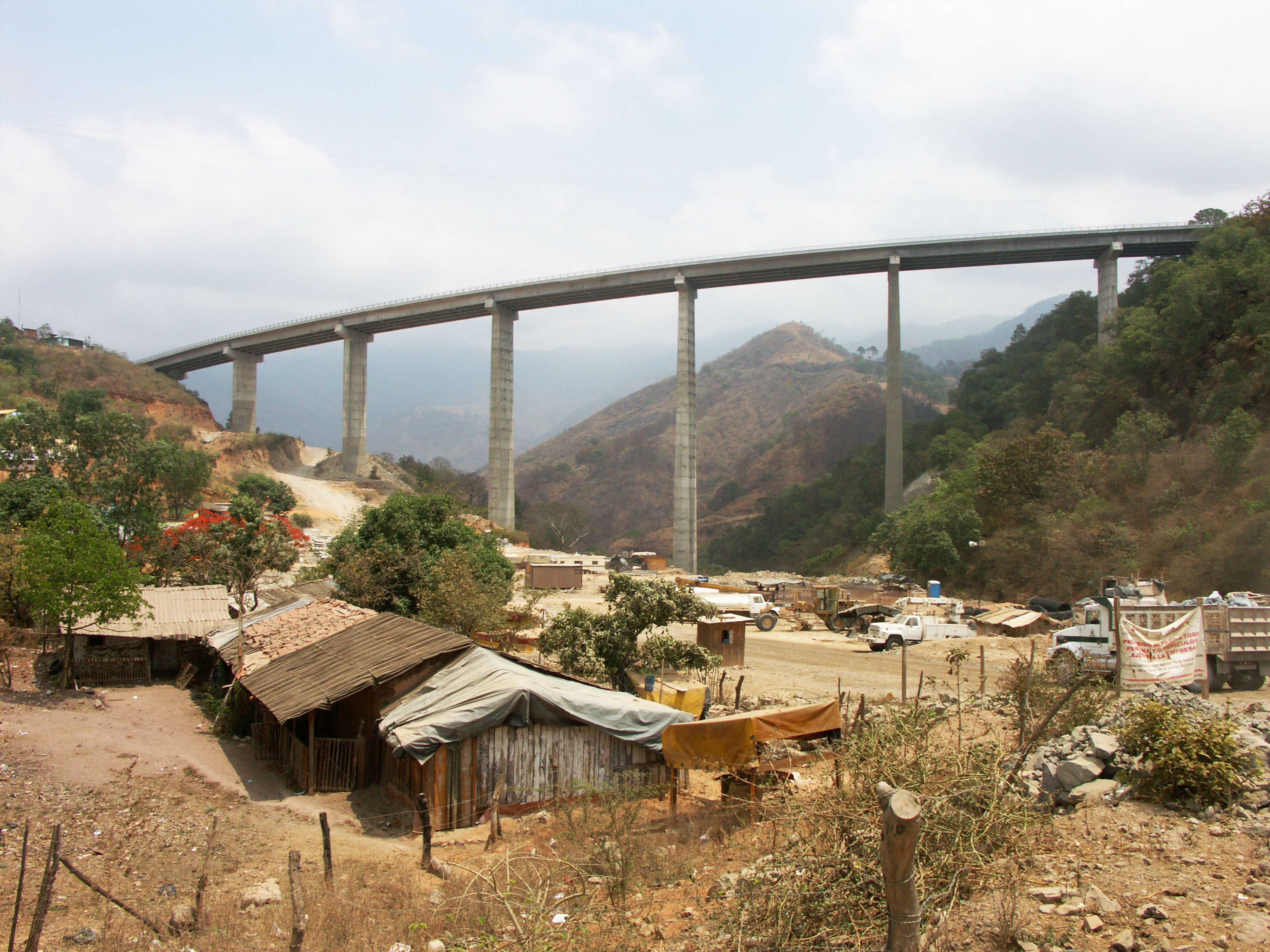
Puente La Capilla en el kilómetro 182. El puente cuenta con 4 claros: uno de 37.5, 2 de 50 y uno de 37.5 metros. Image by Eric Sakowski / HighestBridges.com
Image by Eric Sakowski / HighestBridges.com
Imagen satelital del puente La Capilla.
Túnel justo antes de puente El Nacaral. Image by Eric Sakowski / HighestBridges.com
Puente El Nacaral en el kilómetro 183. El puente cuenta con 8 claros: uno de 37.5, 6 de 50 y uno de 37.5 metros Image by Eric Sakowski / HighestBridges.com
Image by SCT
Construcción del puente El Nacaral. Image by Eric Sakowski / HighestBridges.com
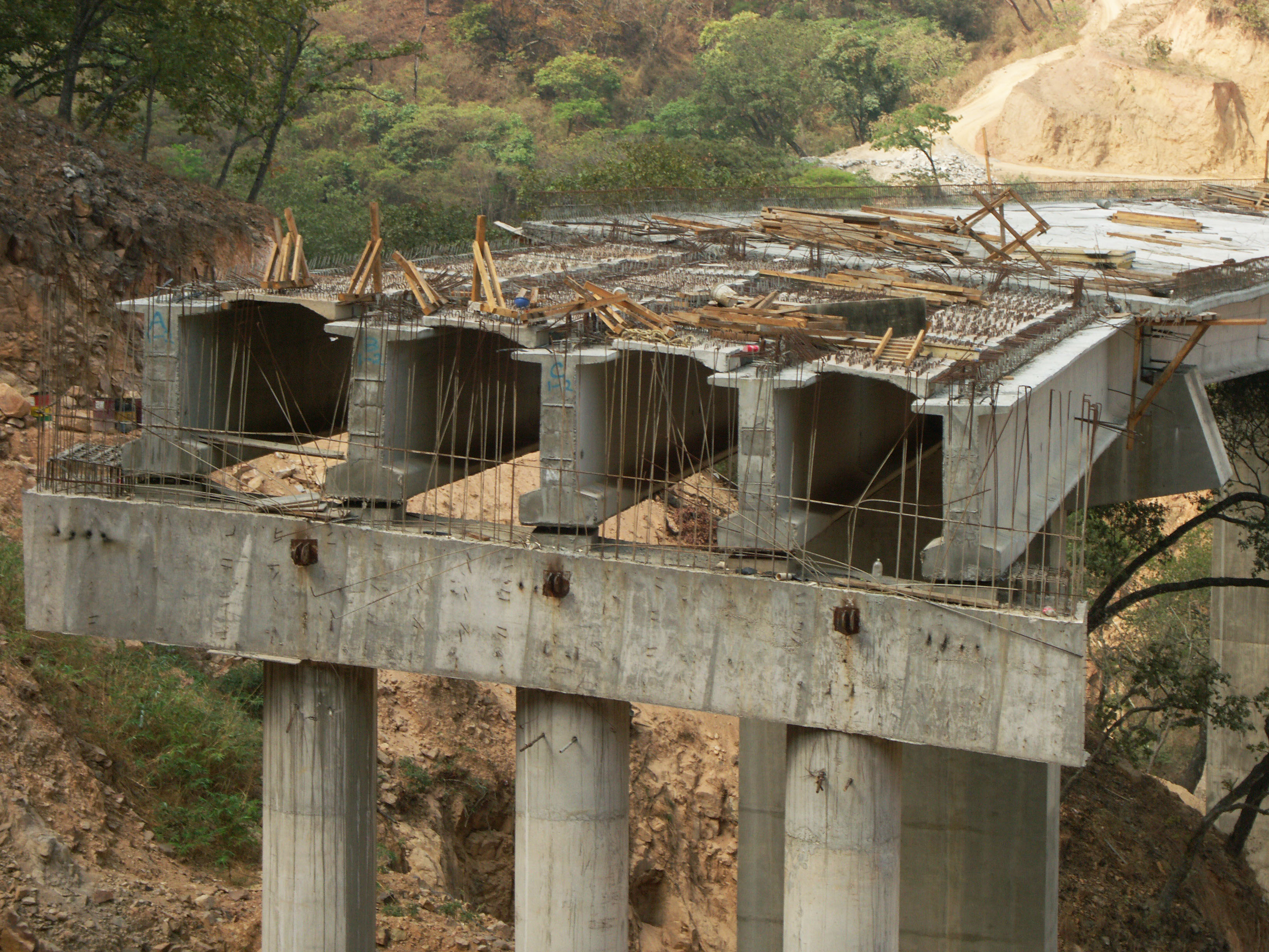
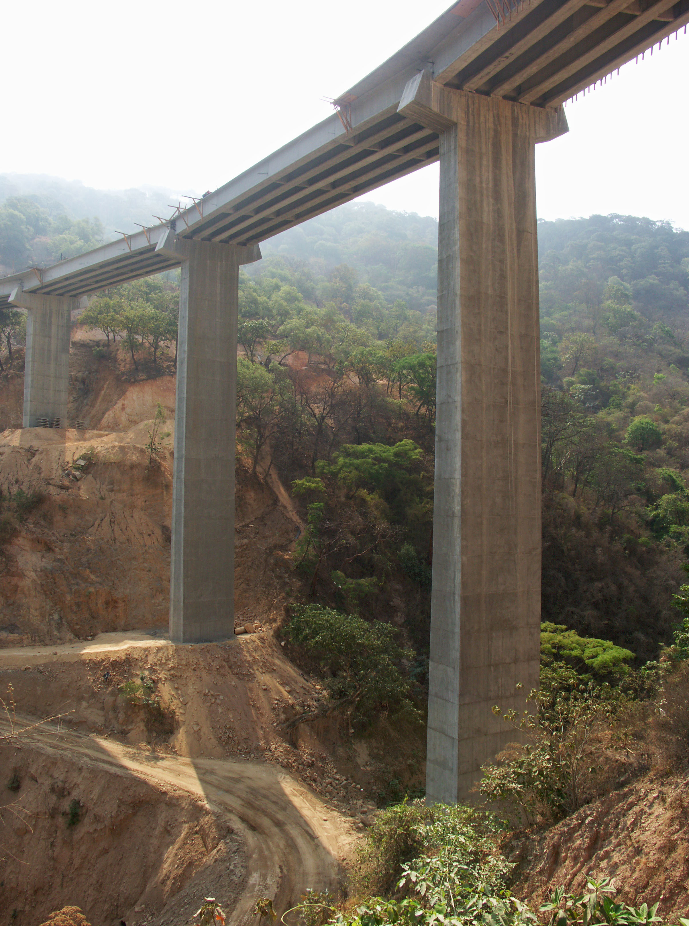
La estandarización de muchos de los puentes se produjo mediante el uso de vigas estilo Nebraska de entre 35 y 55 metros de longitud. Una serie de puentes que fueron diseñados originalmente como doble voladizos fueron rediseñados como de viga Nebraska, permitiendo la reutilización de encofrados que permitieron el ahorro de aproximadamente 15% del costo total de cada estructura. Los túneles fueron también estandarizados con una altura máxima común de 11.7 metros, lo que permitió que los mismos encofrados pudieran ser reutilizados en cualquiera de los 61 túneles.
The standardization of many of the bridges came about by using Nebraska style girders between the length of 35 and 55 meters in length. A number of bridges that were originally designed as double cantilever spans were redesigned as Nebraska girder spans allowing the reuse of formworks that saved the approximate equivalent of 15% of the total cost of each structure. The tunnels were also standardized with a common crown height of 11.7 meters which allowed the same formworks to be reused on any of the 61 tunnels. Image by SCT
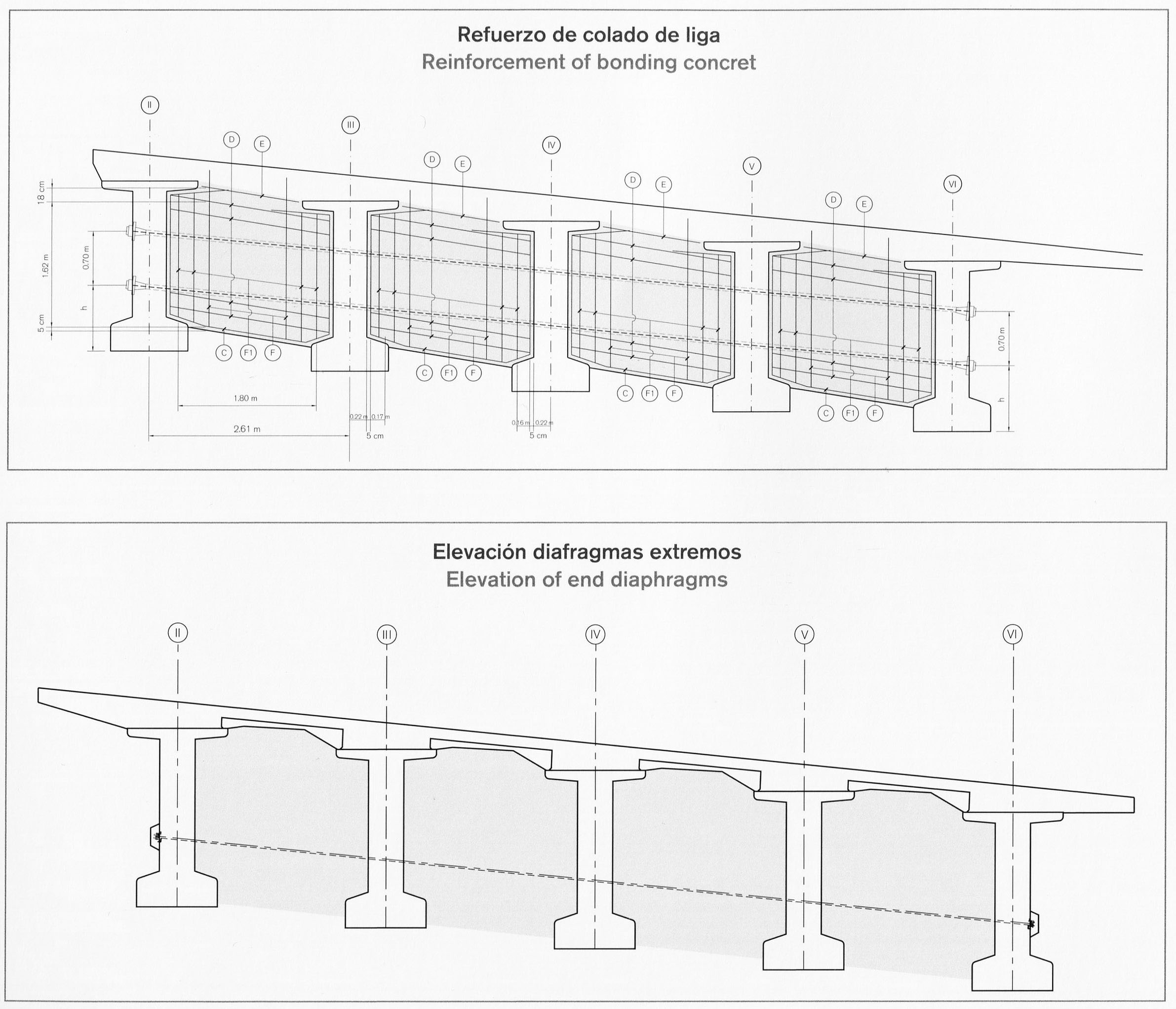
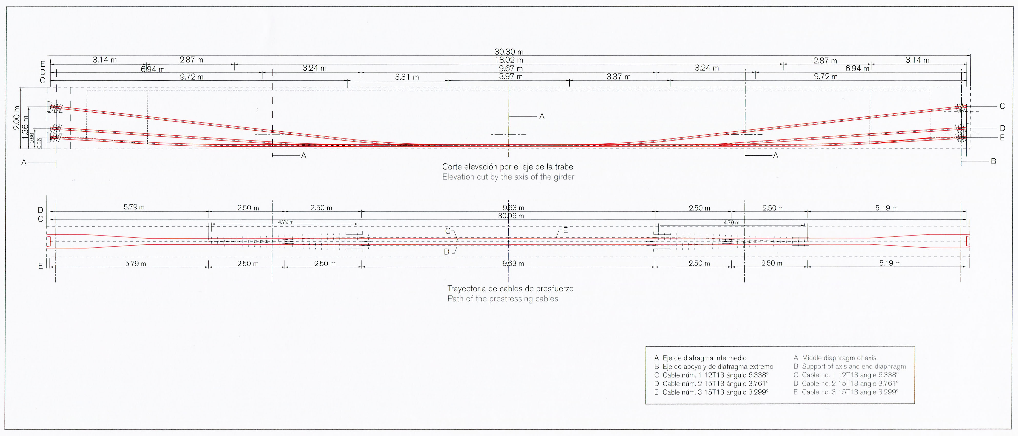
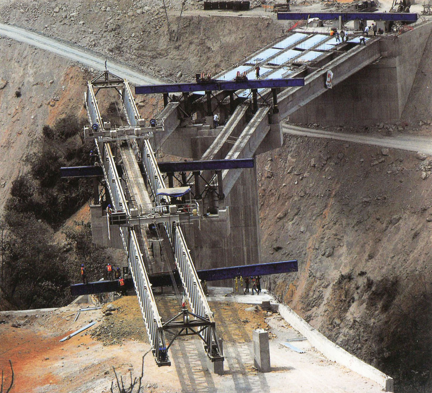
Hay dos procesos básicos para los puentes atirantados. El primero es aplicar la tensión al cable después del vertido de concreto, por ende el término "post-tensado". Los cables están alojados dentro de un tubo y pueden curvarse para controlar y variar la posición de la fuerza de tensado. El segundo tipo es "pre-tensado" donde los cables se tensan antes de verter el concreto y liberados después de que se ha endurecido.
There are two basic processes to prestressed bridges. The first is to apply the cable tensioning after the concrete pouring hence the term “post-tensioned”. Cables are housed inside of a pipe and can be curved to control and vary the position of the prestressing force. The second type is “pre-tensioned” where the cables are tensioned prior to concrete pouring and released after the concrete has hardened. Image by SCT
Las vigas de tipo Nebraska en la carretera Durango-Mazatlán tienen profundidades que van desde los 1.8 hasta los 2.4 metros, cubriendo claros de entre 38 y 50 metros.
The Nebraska-type beams on the Durango-Mazatlan highway have depths ranging from 1.8 to 2.4 meters covering spans between 38 and 50 meters. Image by SCT
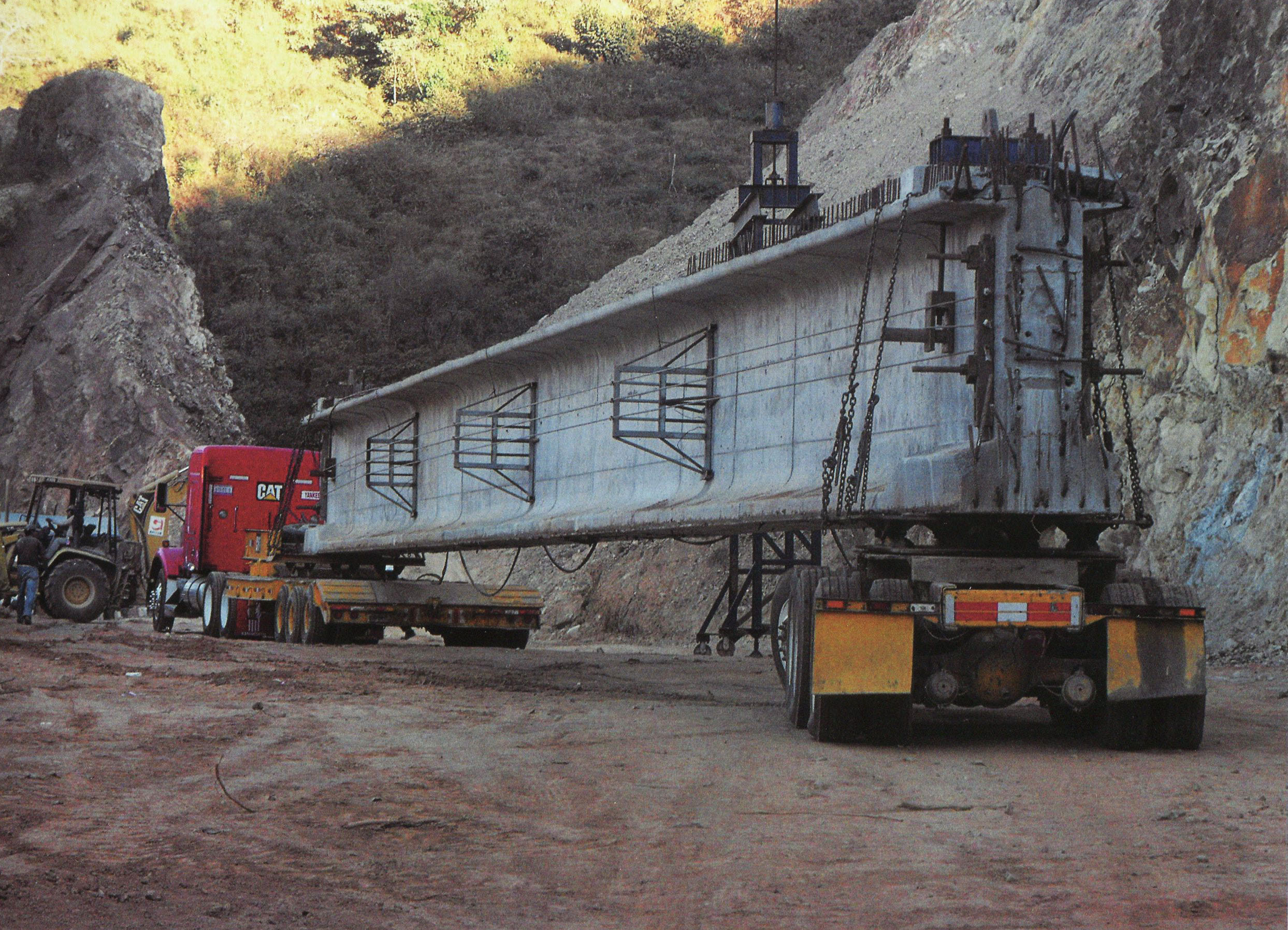
Una vez que el concreto en el viga alcanza el 80% de su resistencia, los cables son tensados y los extremos del cable se cortan y pulen. La lechada se bombea entonces en los ductos y la viga está lista para ser transportada y montada. Las vigas pueden pesar hasta 110 toneladas.
Once the concrete in the beam reaches 80% of its strength, the cables are prestressed and the ends of the cable are cut and then polished. Grout is then pumped into the ducts and the girder is ready to be transported and mounted. The beams can weigh as much as 110 tons. Image by SCT
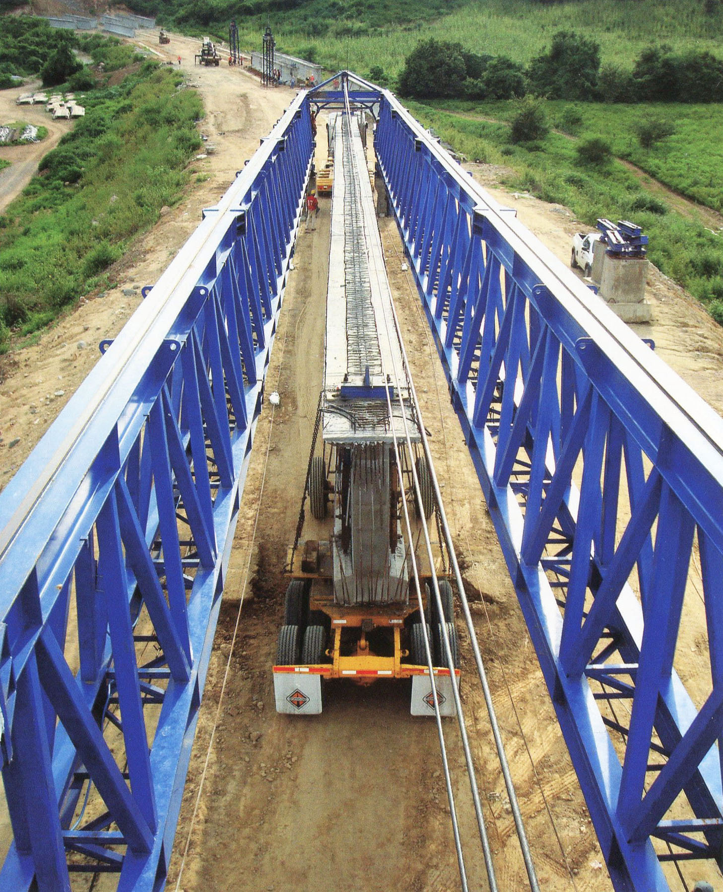
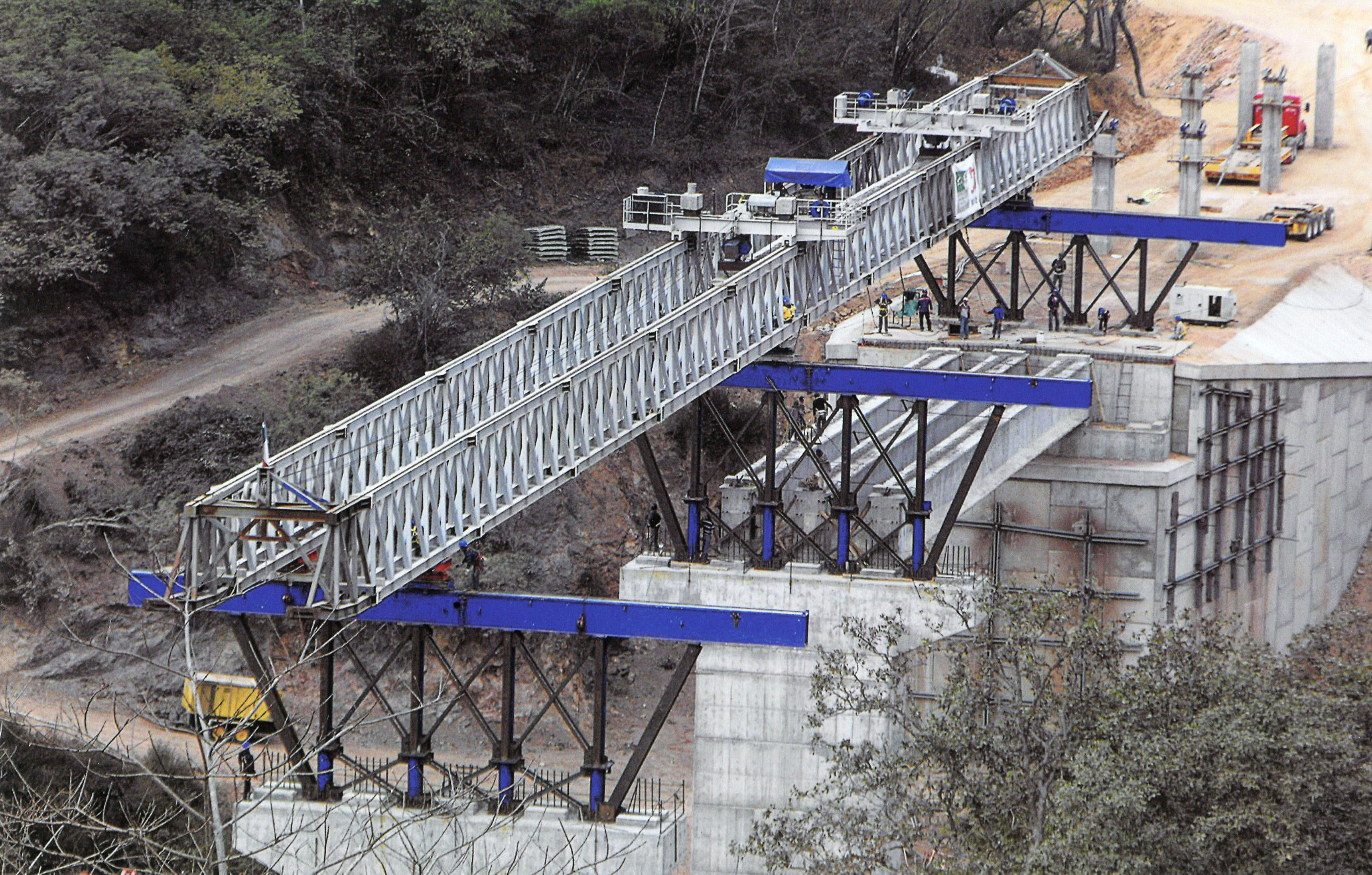
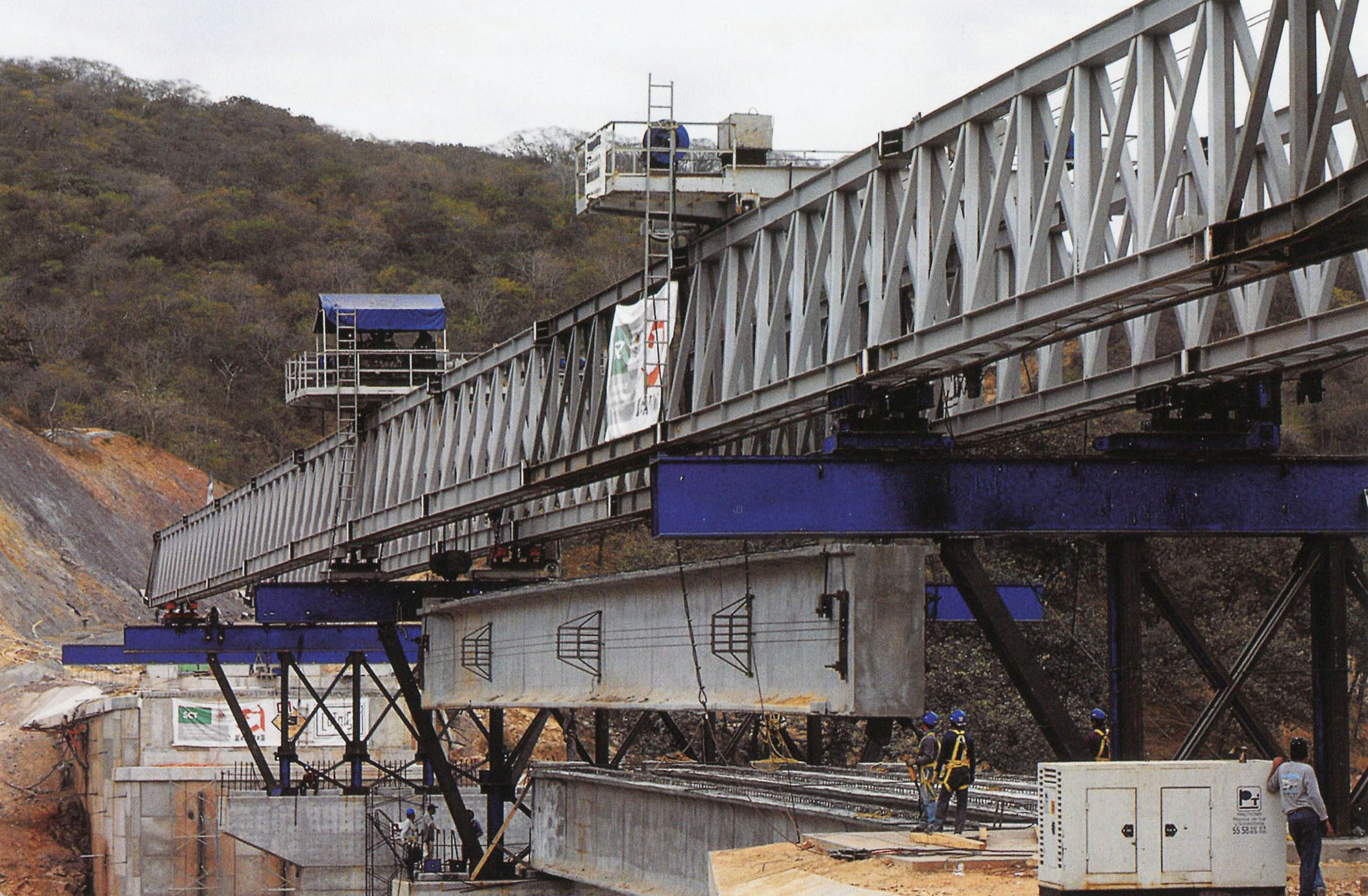
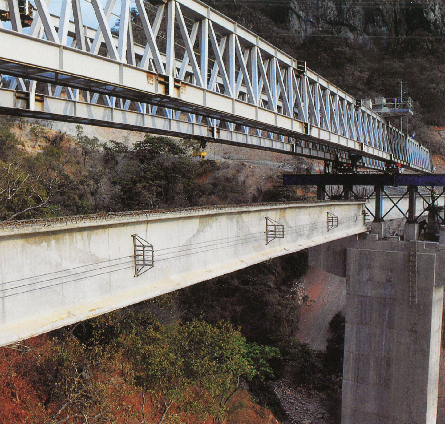
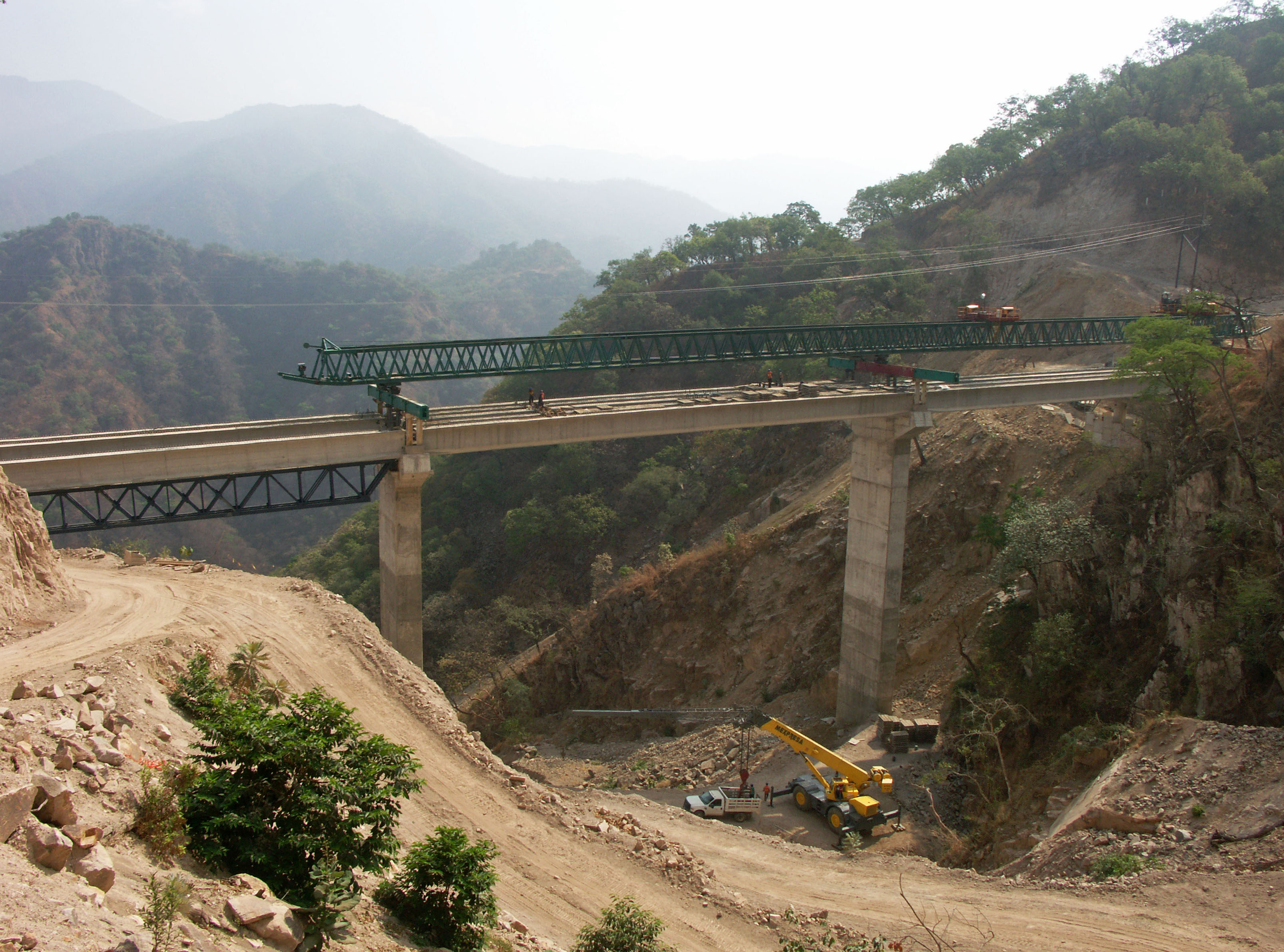
Completed girders are launched with a traveling truss system. Las vigas son instaladas con un sistema de viga lanzadora. Image by SCT
Image by SCT
Image by SCT
La lanzadora de vigas también debe negociar curvas en los puentes.
The truss bridge traveler must also negotiate curved bridges. Image by SCT
Puente El Nacaral. Image by Eric Sakowski / HighestBridges.com
Imagen satelital del puente El Nacaral.
Puente Las Palomas en el kilómetro 184. El puente cuenta con 3 claros de: 37.5, 50 y 37.5 metros. Image by Eric Sakowski / HighestBridges.com
Imagen satelital del puente Las Palomas.
Puente Jabalina en el kilómetro 185. El puente cuenta con 5 claros: uno de 37.5, 3 de 50 y uno de 37.5 metros. Image by Eric Sakowski / HighestBridges.com
Image by Eric Sakowski / HighestBridges.com
Imagen satelital del puente Jabalina.
Puente Pánuco en el kilómetro 185. El puente cuenta con 5 claros: uno de 37.5, 3 de 42 y uno de 37.5 metros.Image by Eric Sakowski / HighestBridges.com
Pilas del puente Pánuco. Image by Eric Sakowski / HighestBridges.com
Imagen satelital del Puente Pánuco.
Puente La Guayanera. El puente cuenta con 3 claros de: 50.72, 51.37 y 50.72 metros. Image by Eric Sakowski / HighestBridges.com
Imagen salital del Puente La Guayanera.
Túneles Las Charcas y Palomas en los kilómetro 189 y 190. Image by SCT
Túnel Copala II en el kilómetro 192. Image by Eric Sakowski / HighestBridges.com
Puentes en los kilómetros 195 - 206
Puente Sin Nombre en el kilómetro 196. El puente cuenta con 3 claros de: 42, 50 y 42 metros. Image by SCT
Imagen satelital del puente Sin Nombre en el kilómetro 196.
Puente Sin Nombre en el kilómetro 201. El puente cuenta con 3 claros de: 40.65, 51.3 y 40.65 metros. Image by SCT
Puente Sin Nombre en el kilómetro 204. El puente cuenta con 9 claros de: 10.34, 22.68, 10.34, 29.24, 3 de 30, 29.58 y 7.88 metros. Image by SCT
Puentes de la Carretera Durango-Mazatlán
Image by SCT
Túneles de la Carretera Durango-Mazatlán
Image by SCT
¡Felicitaciones a las empresas involucradas en la construcción de la carretera!
