Chirajara Bridge
Chirajara Bridge
Viaducto Chirajara
Guayabetal, Cundinamarca, Colombia
512 feet high / 156 meters high
630 foot span / 192 meter span
2023
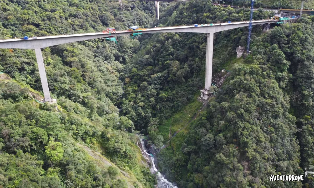
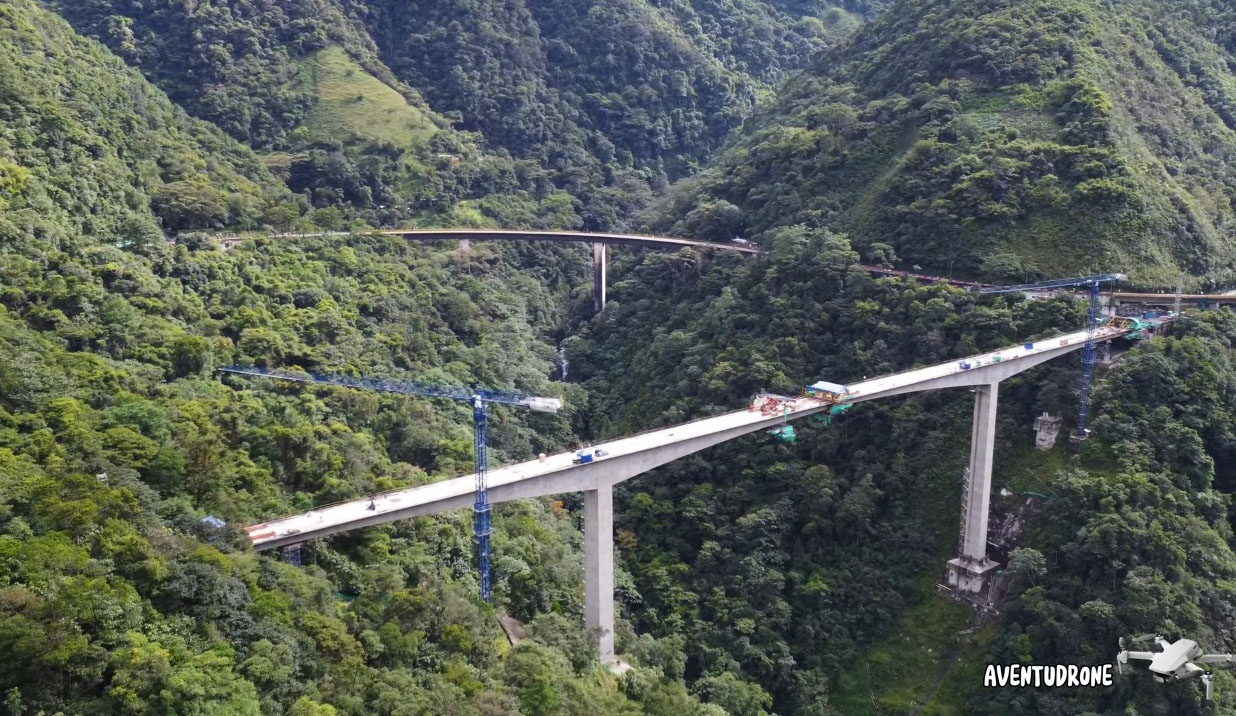
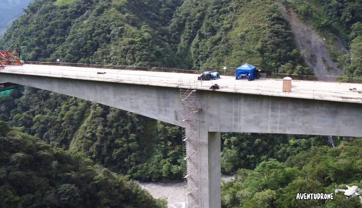
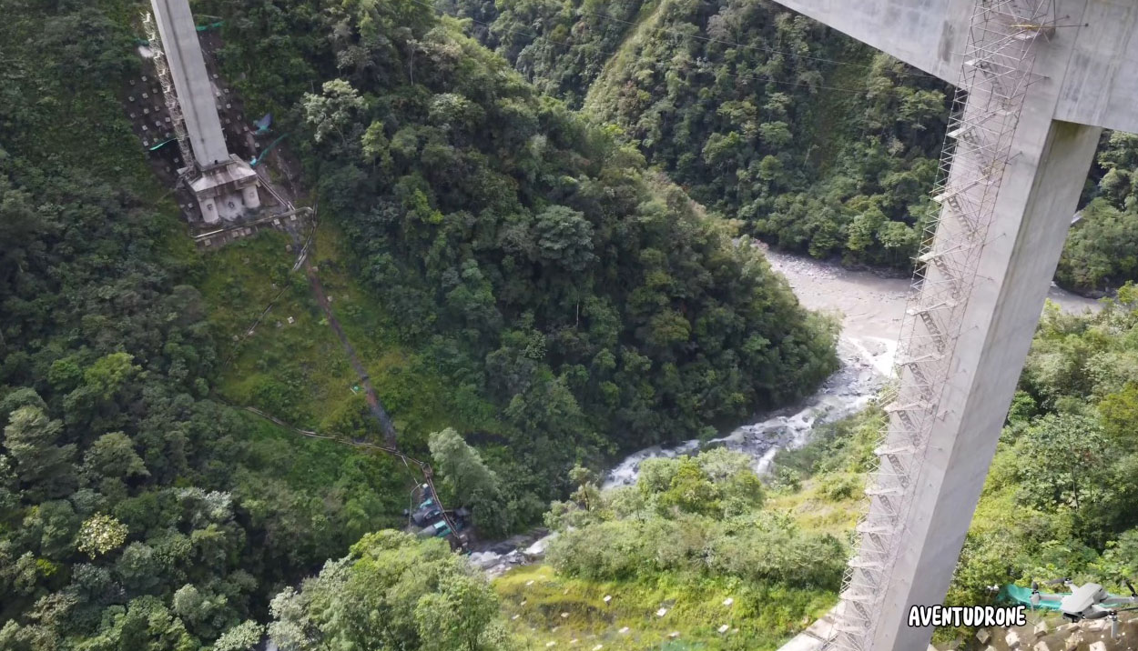
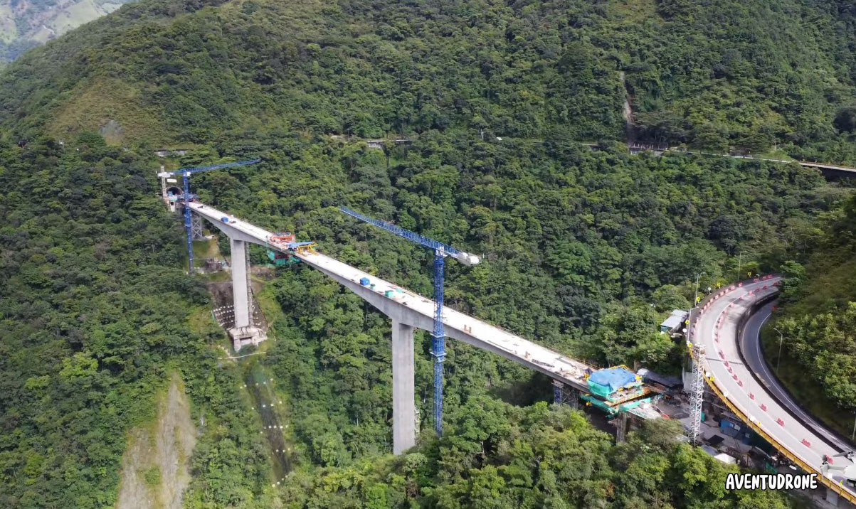
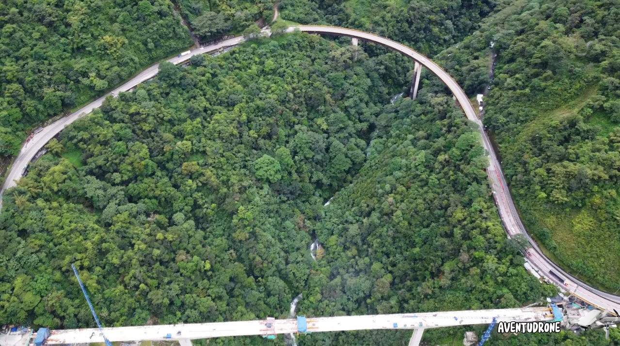
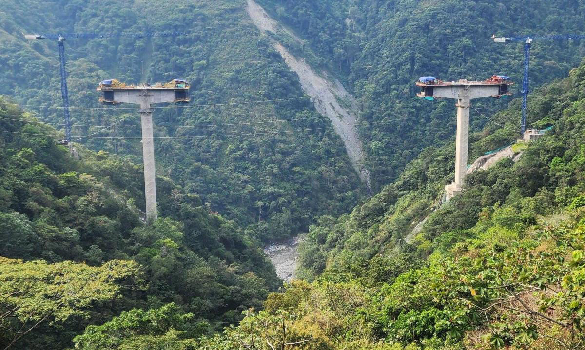
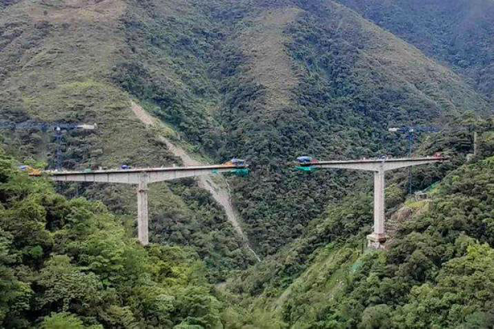
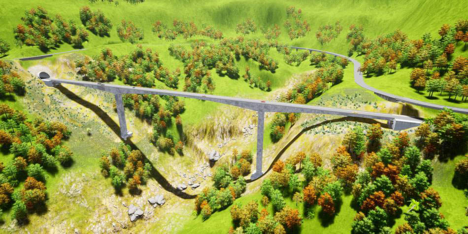
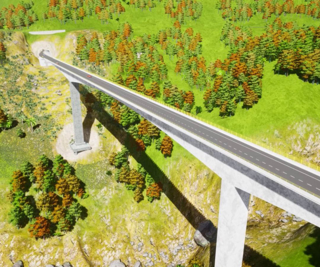
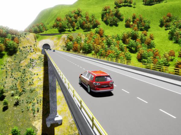
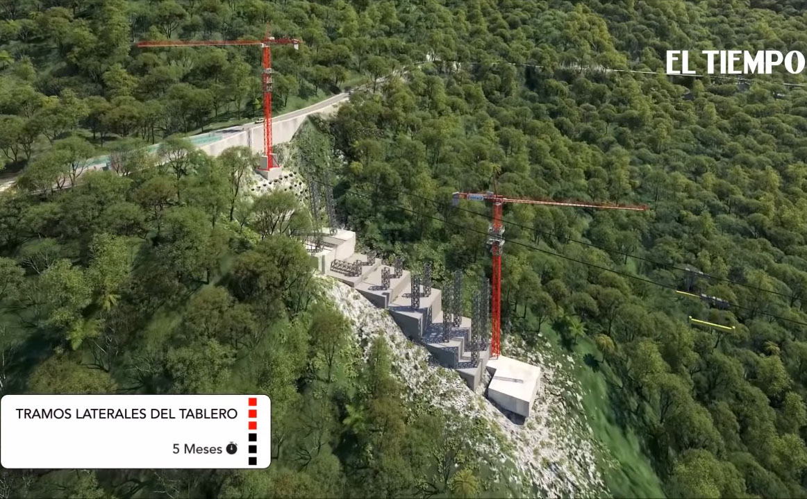
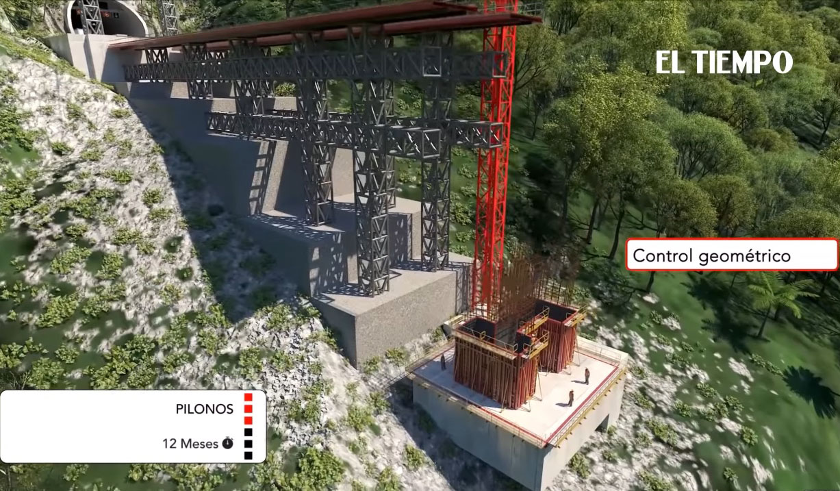
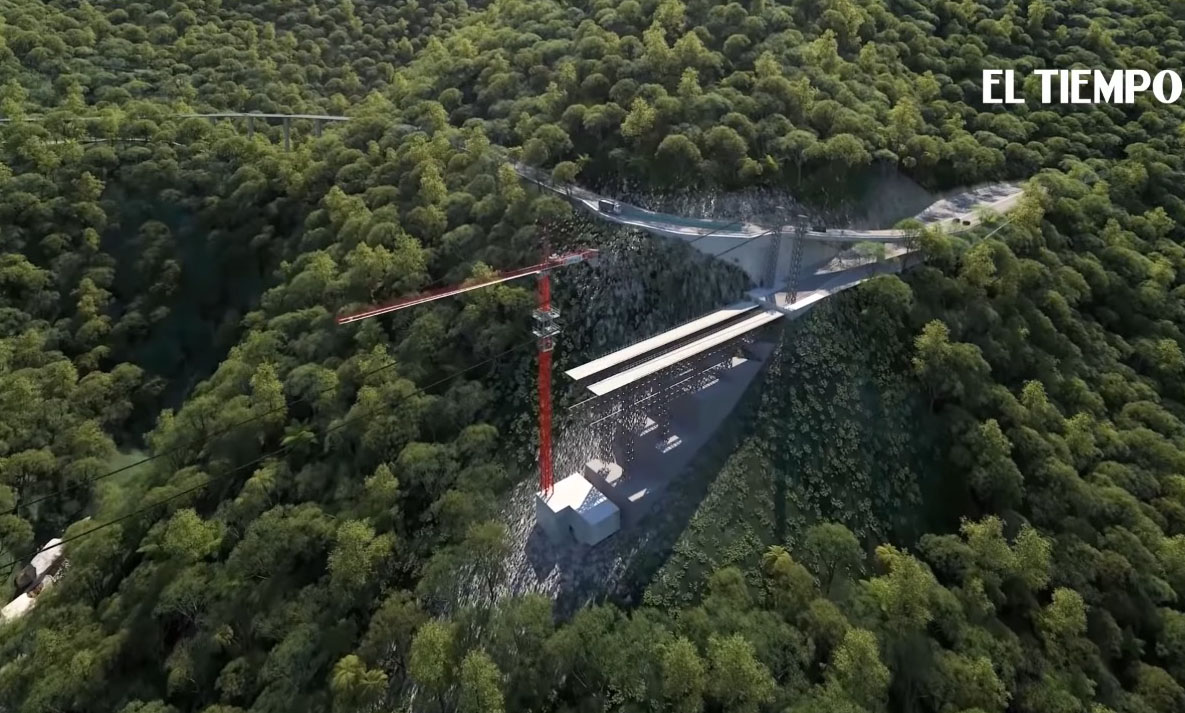
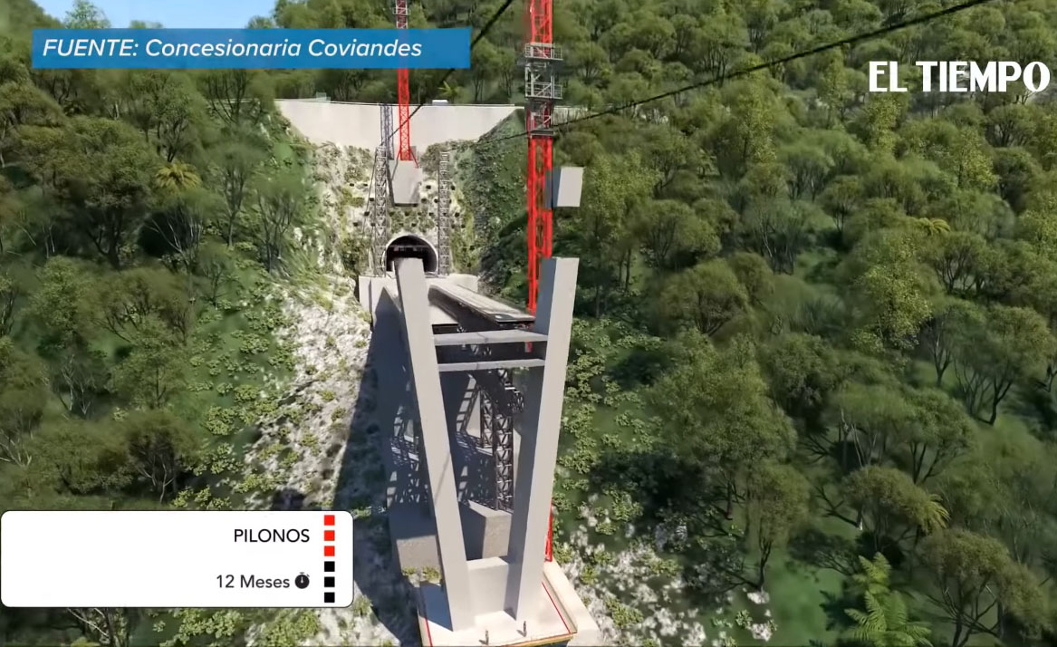
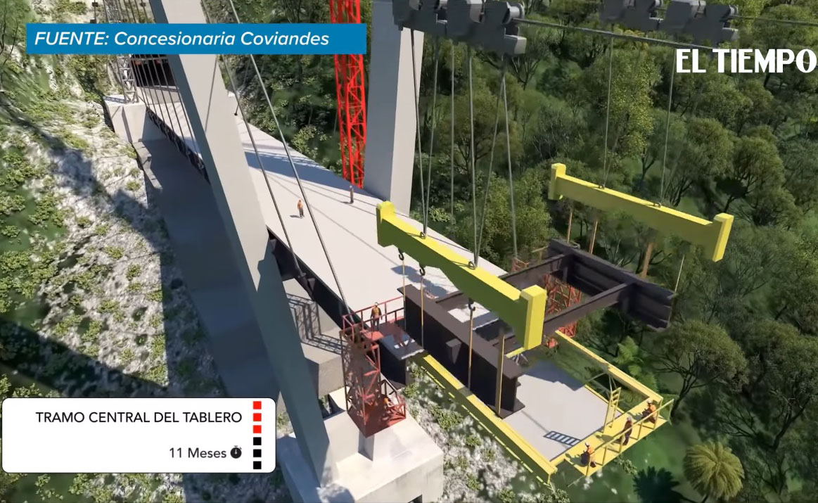
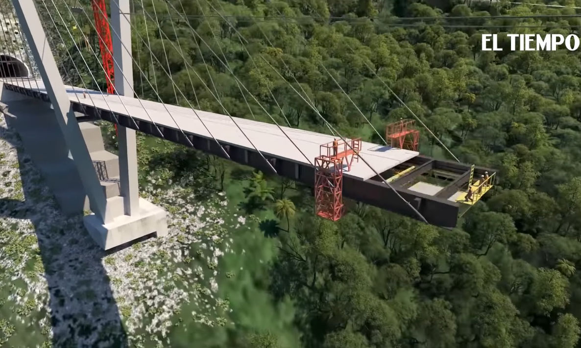
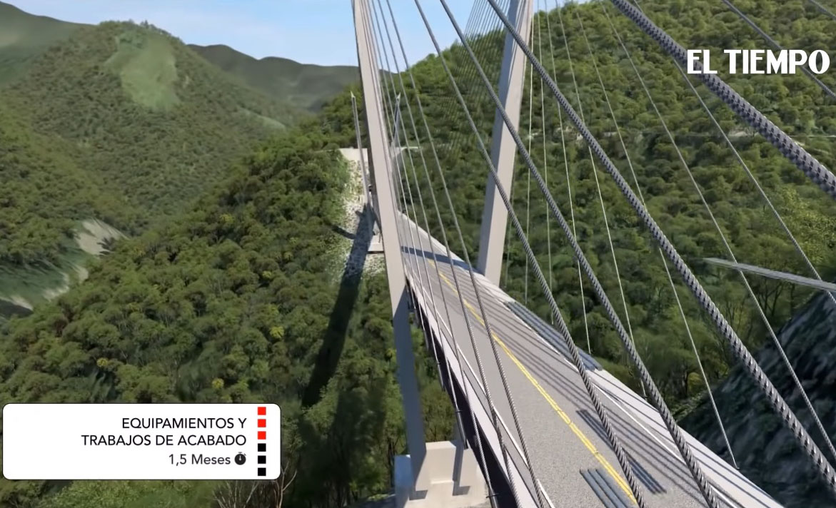
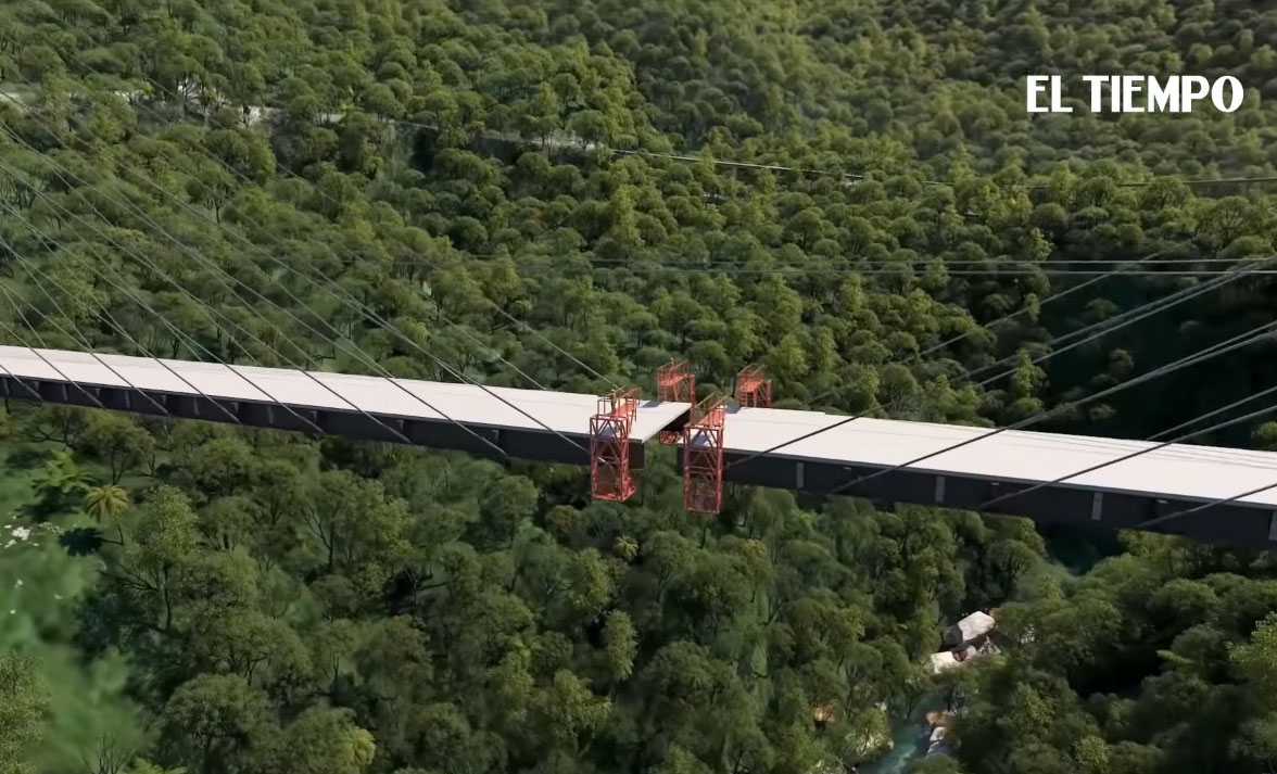
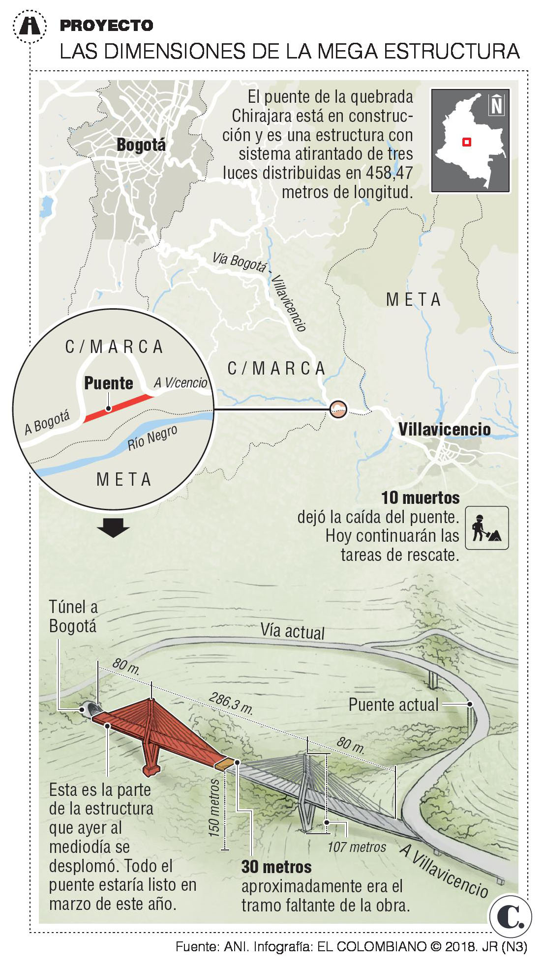
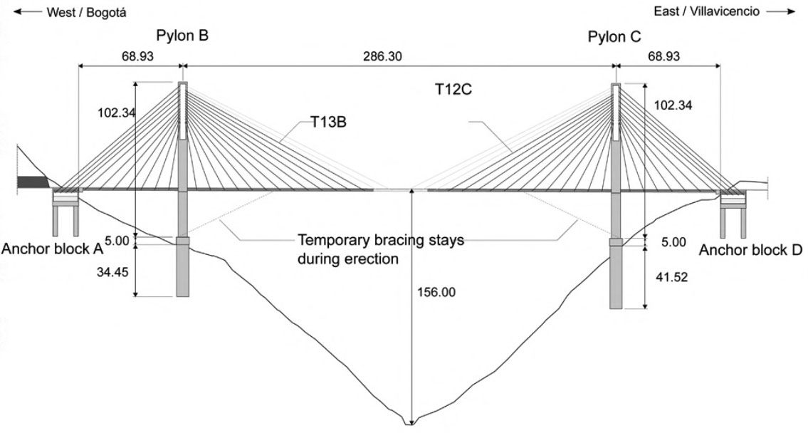
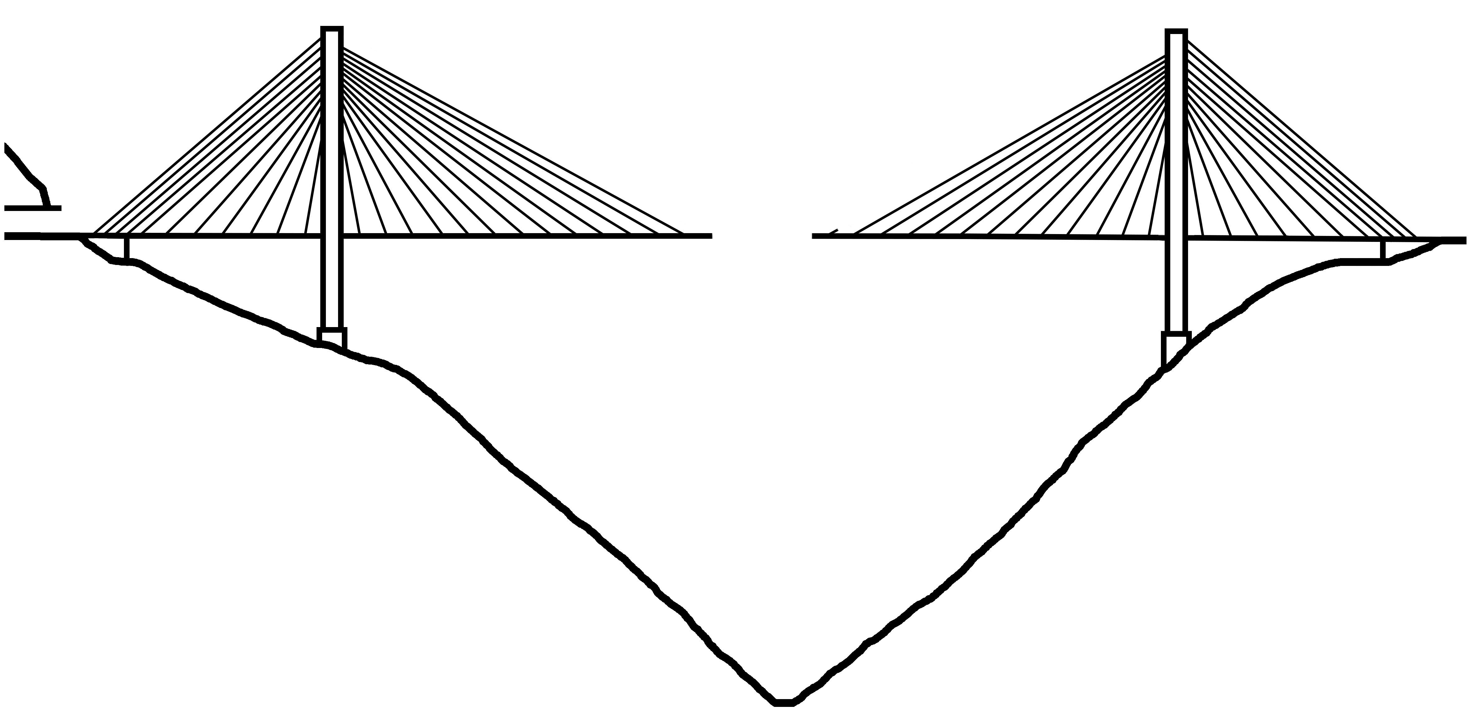
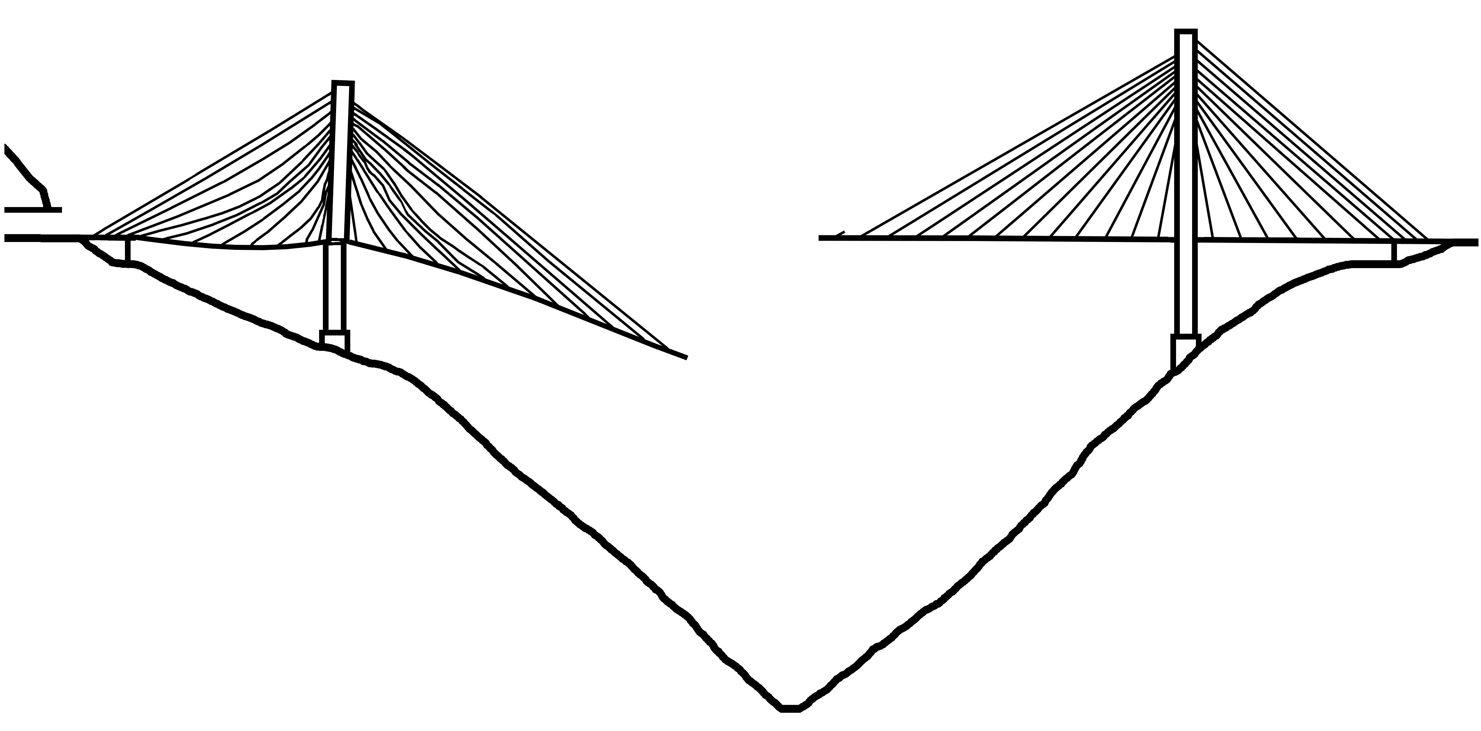
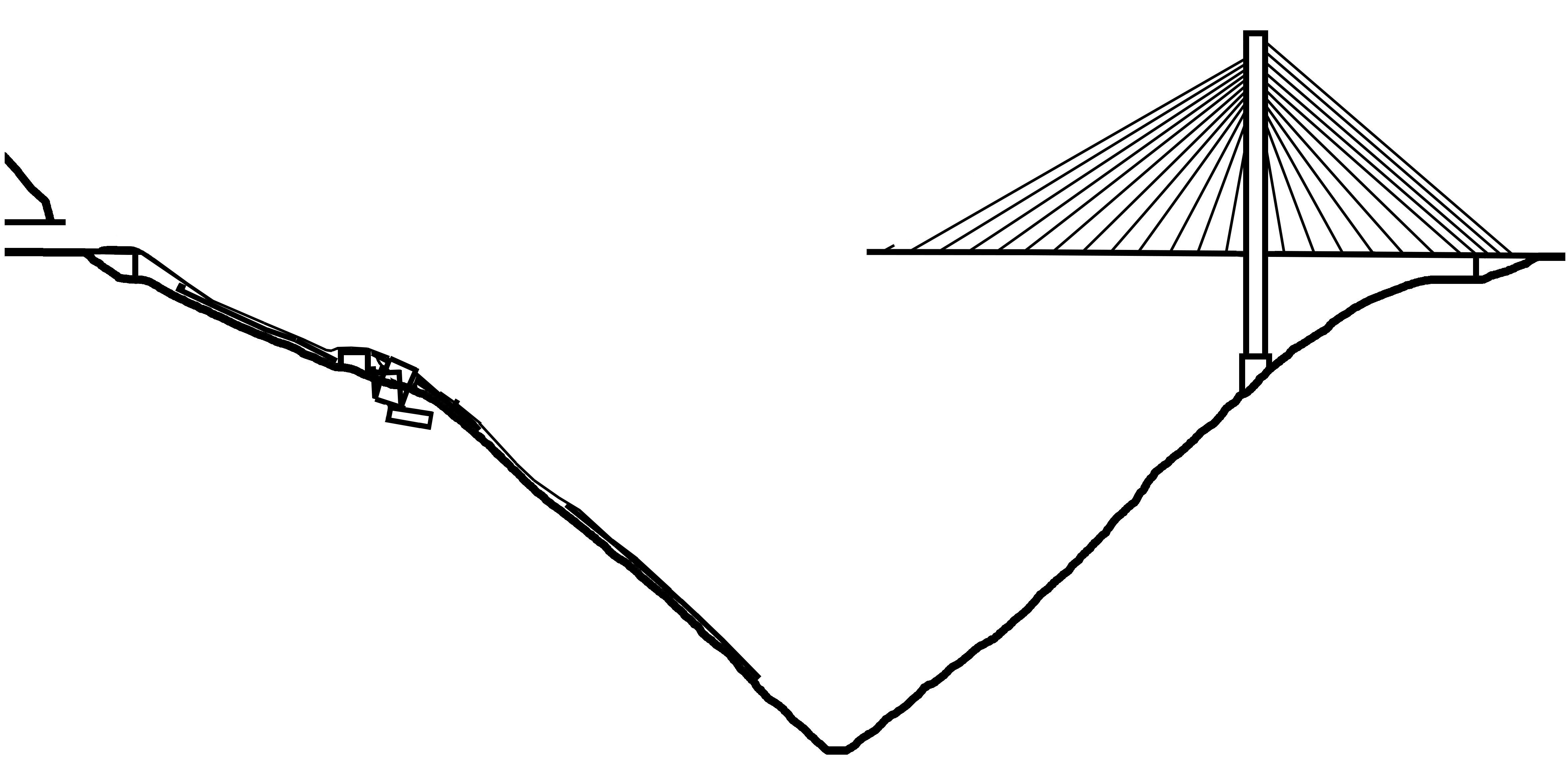
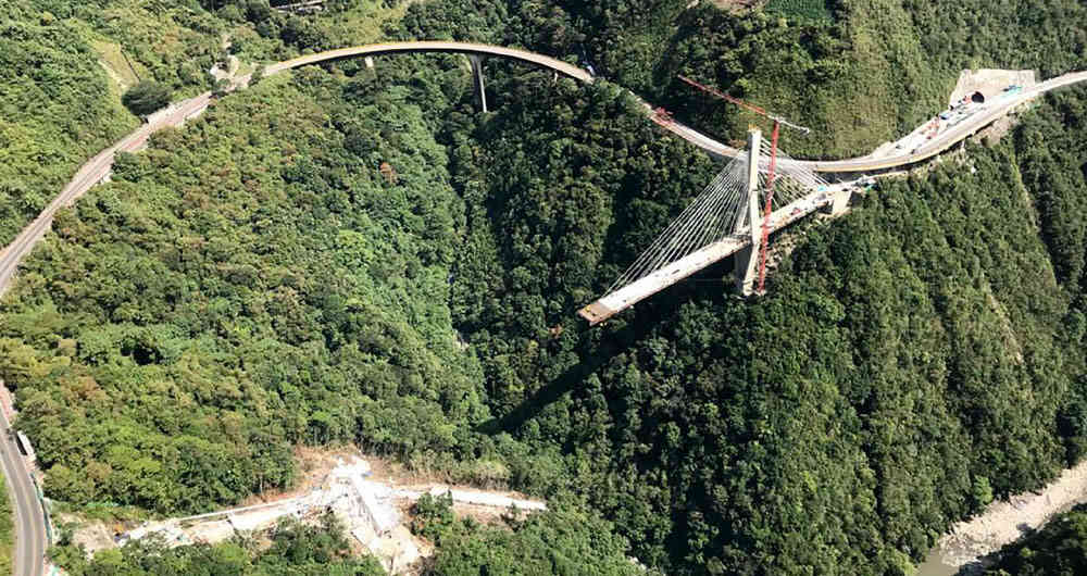
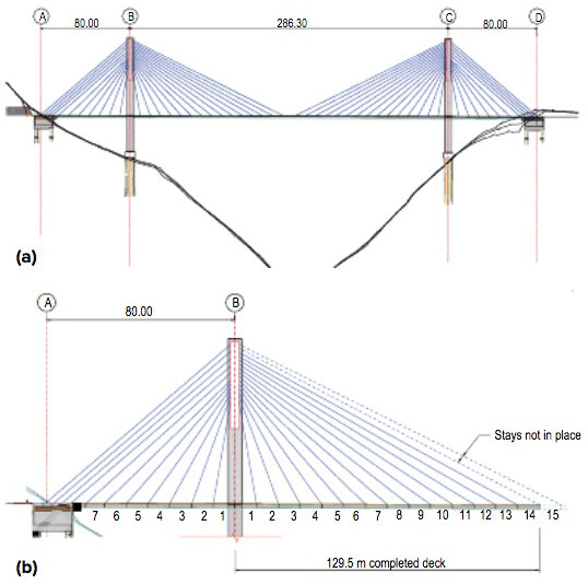
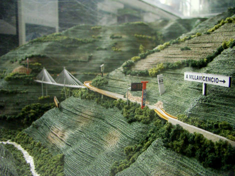
Chirajara Bridge is the highest bridge in Colombia with a deck 156 meters above a forested creek that flows into the great Rio Negro River gorge along the Bogota-Villavicencio highway. Originally to be a cable stayed bridge, the final design is a cantilevered concrete beam bridge with a total length of 460 meters with a span configuration of 114.6 +192 +114.6 meters on piers 73 and 54 meters tall.
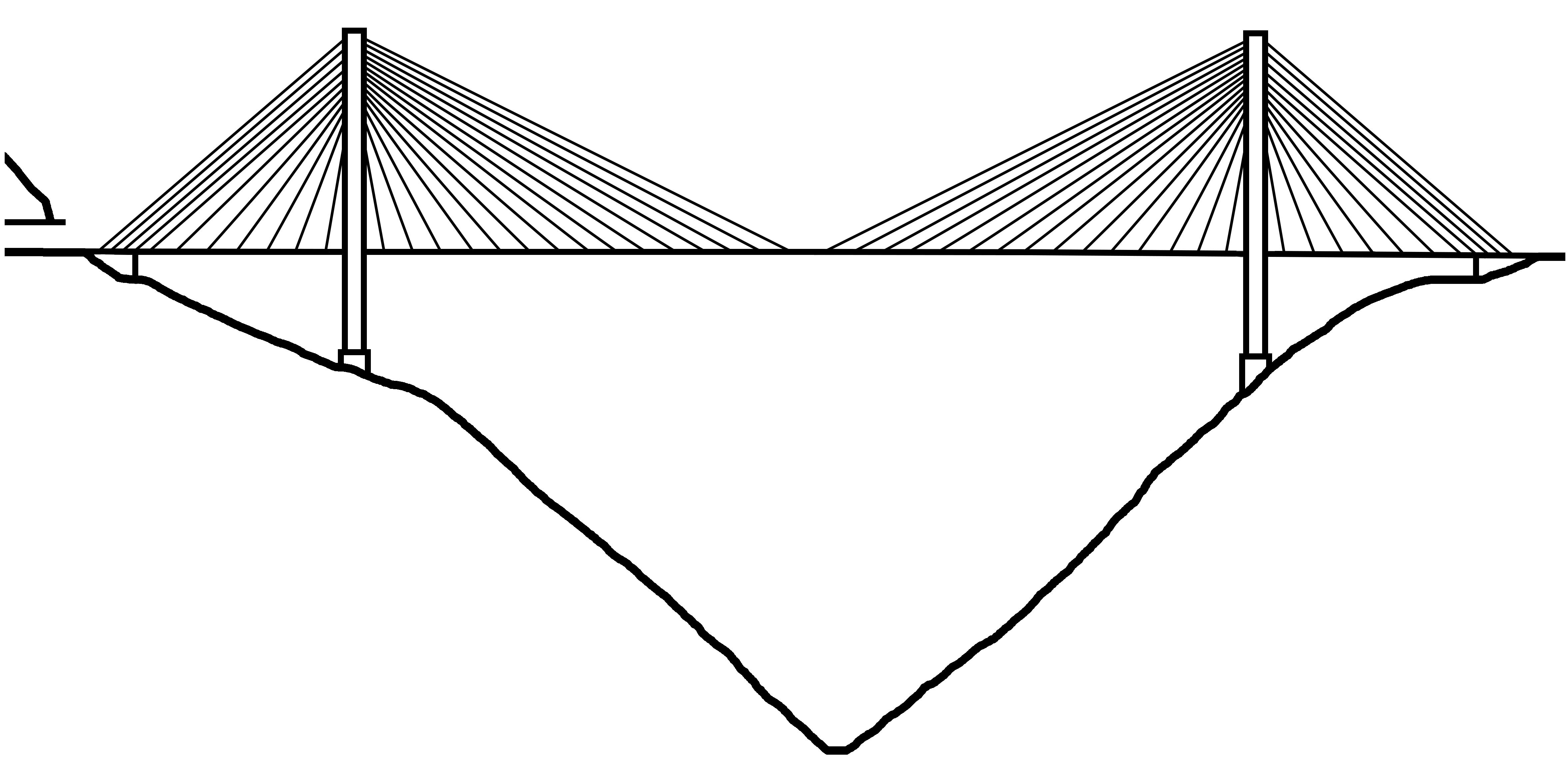
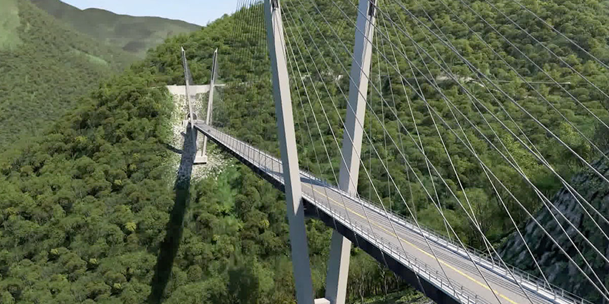
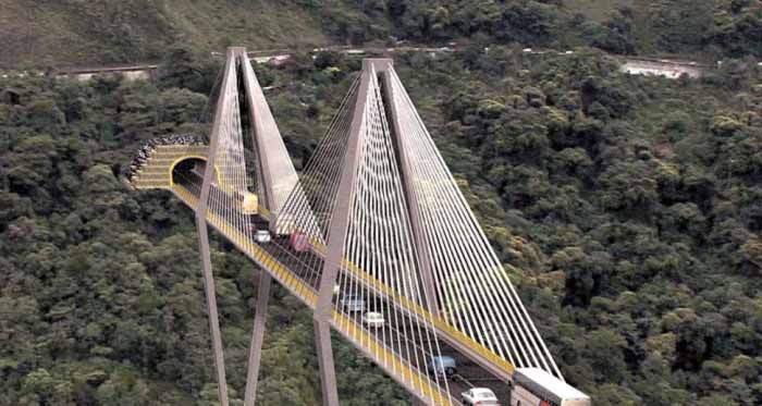
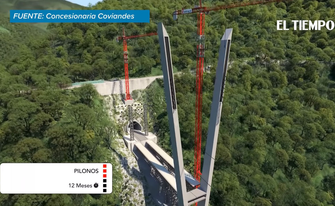
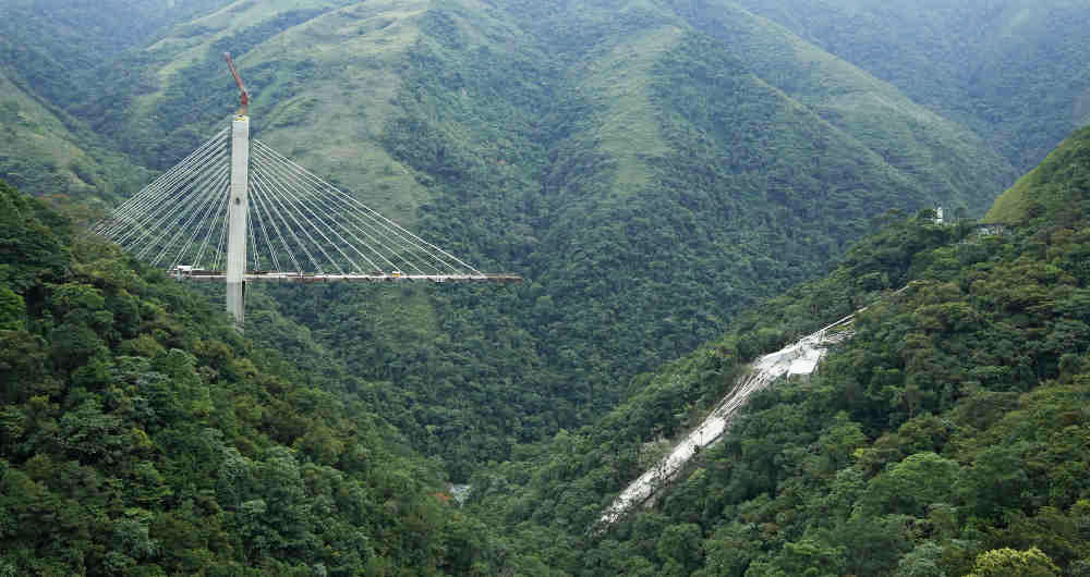
The new beam design came after a V-shaped cable stayed configuration was scrapped as the replacement for the original diamond shaped cable stayed tower that collapsed in 2018. This accident forever tarnished the once perfect track record of zero cable stayed bridge collapses stretching back more then 60 years to the first modern cable stayed span from 1957.
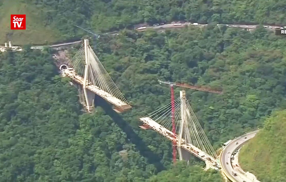
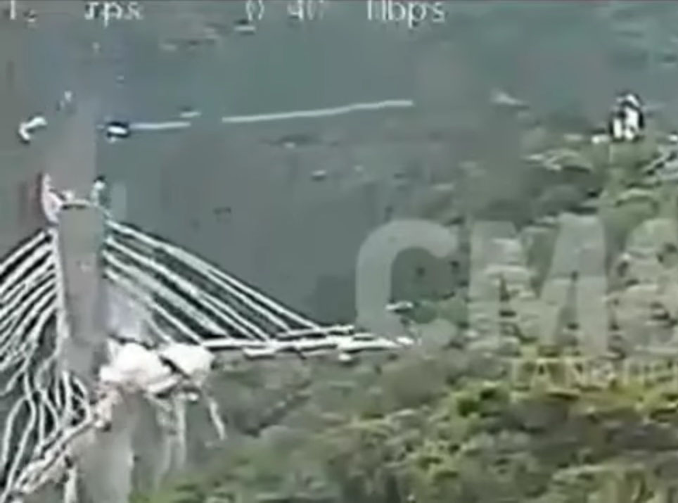
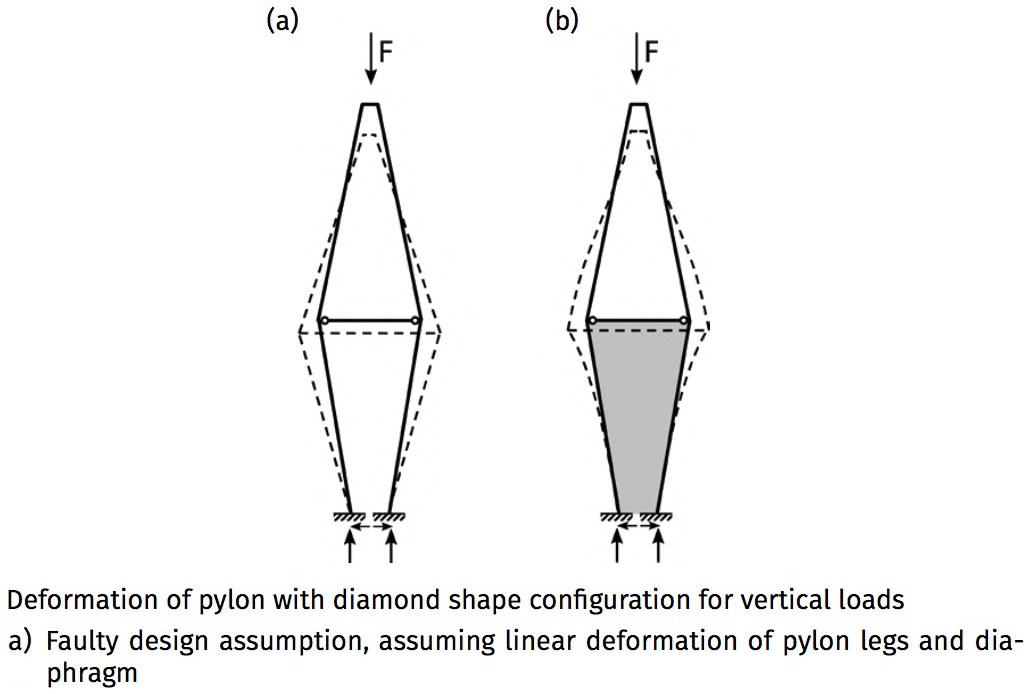
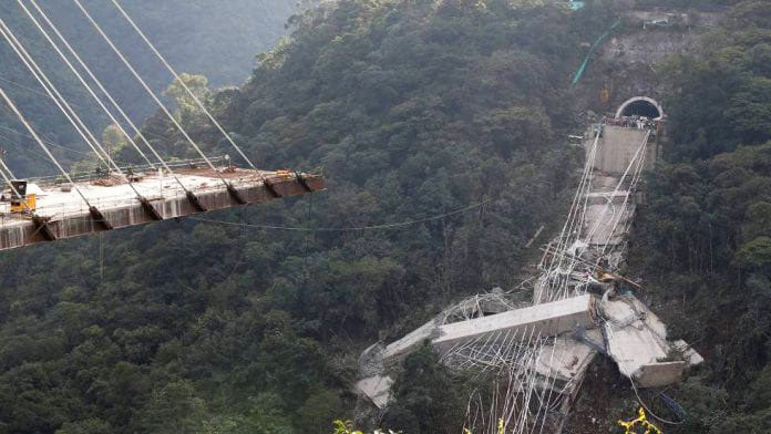
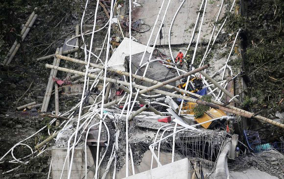
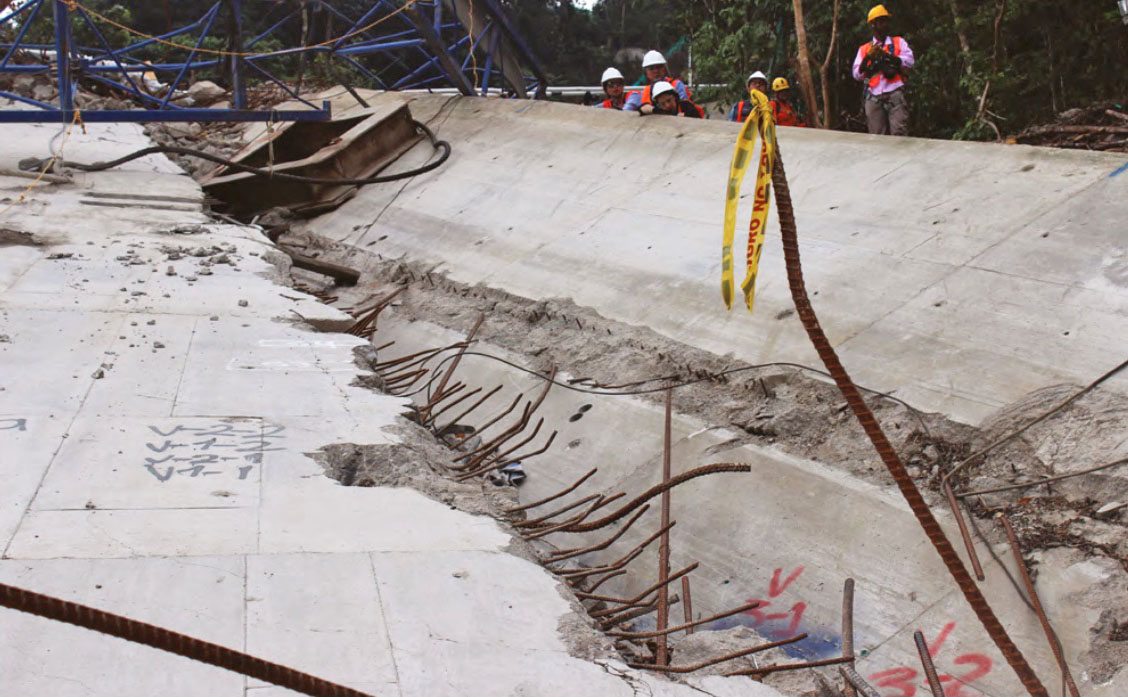
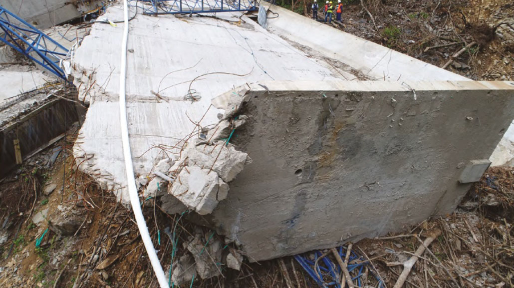
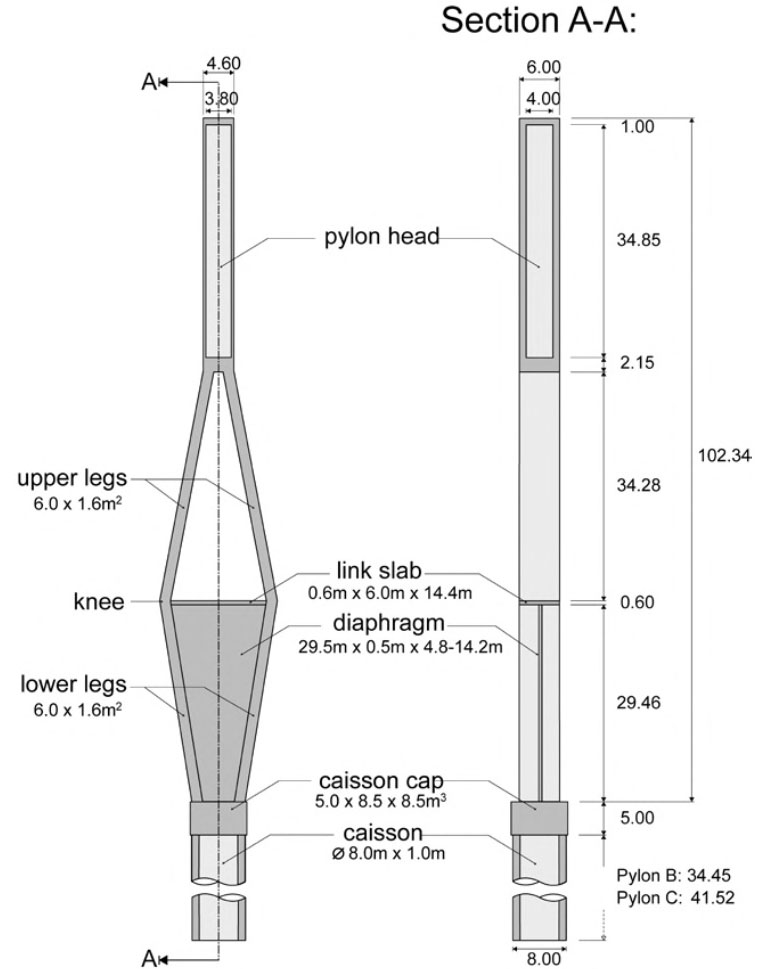
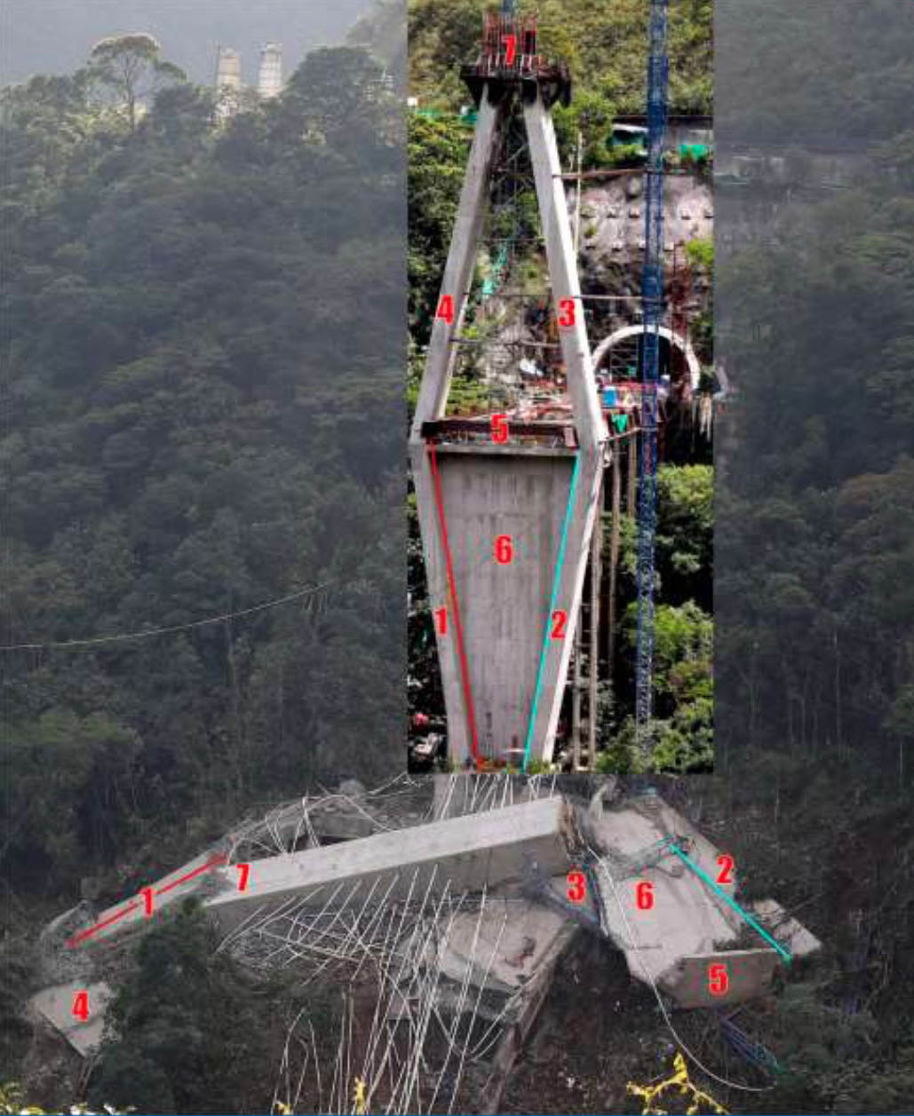
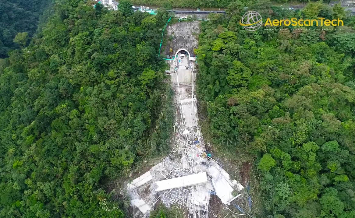
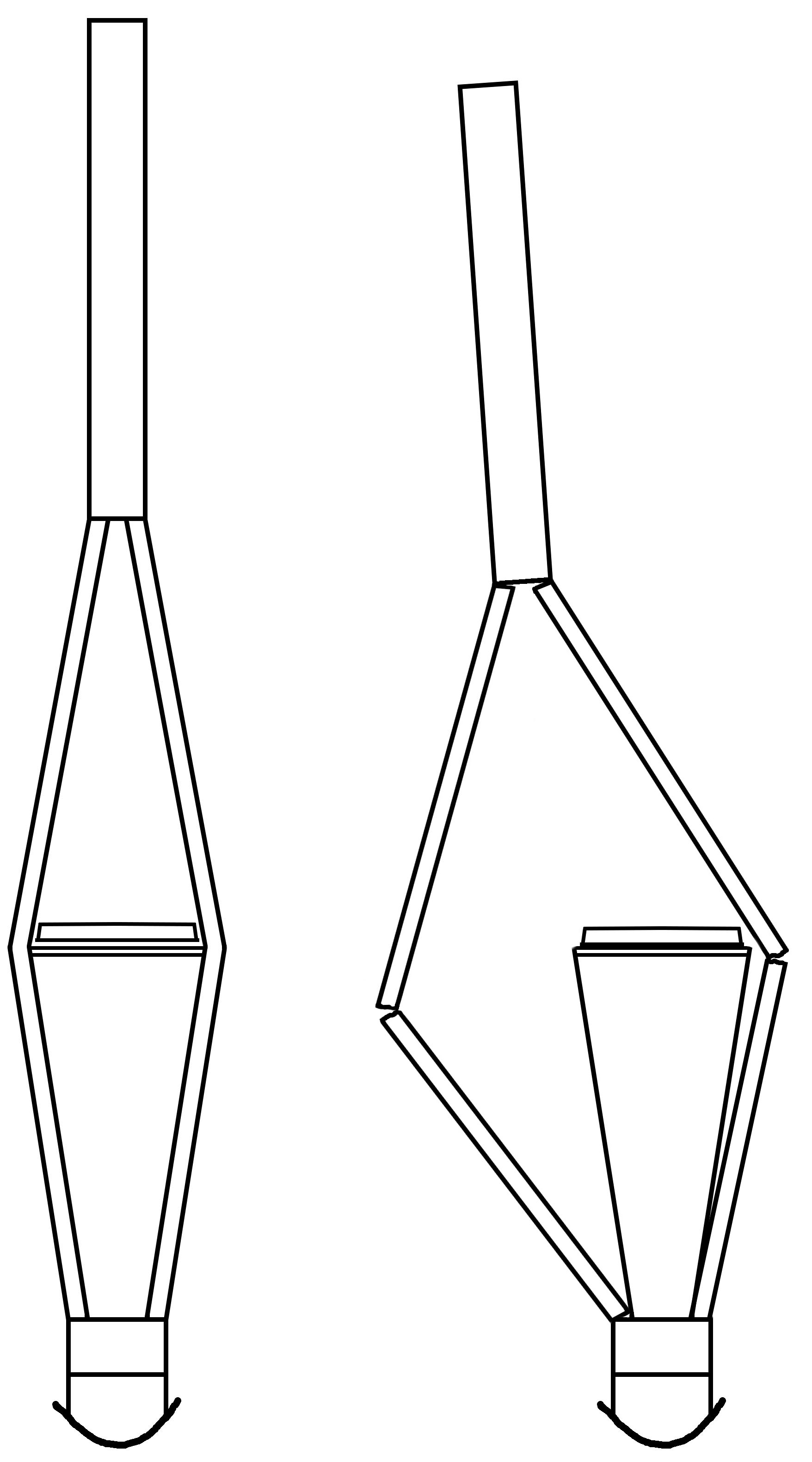
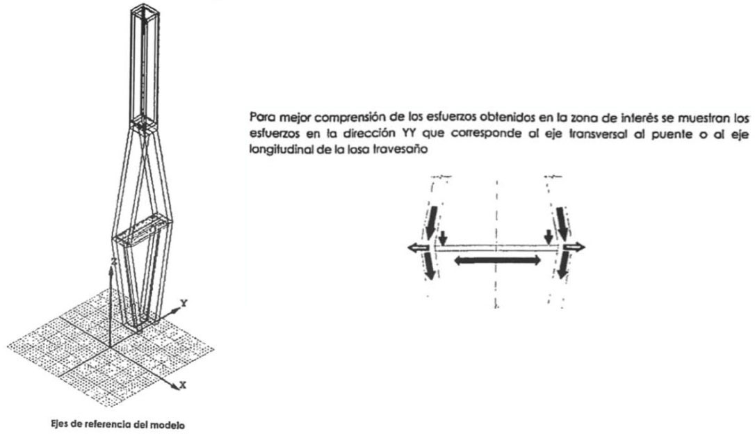
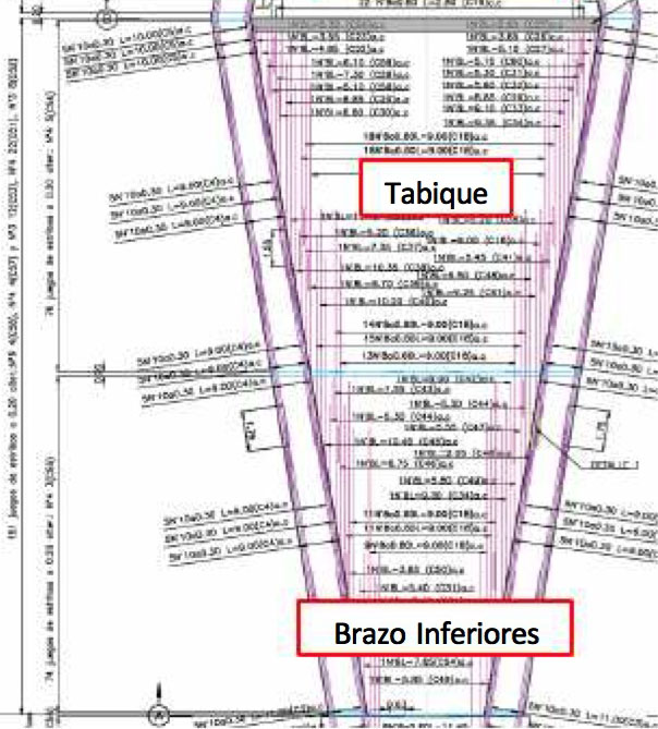
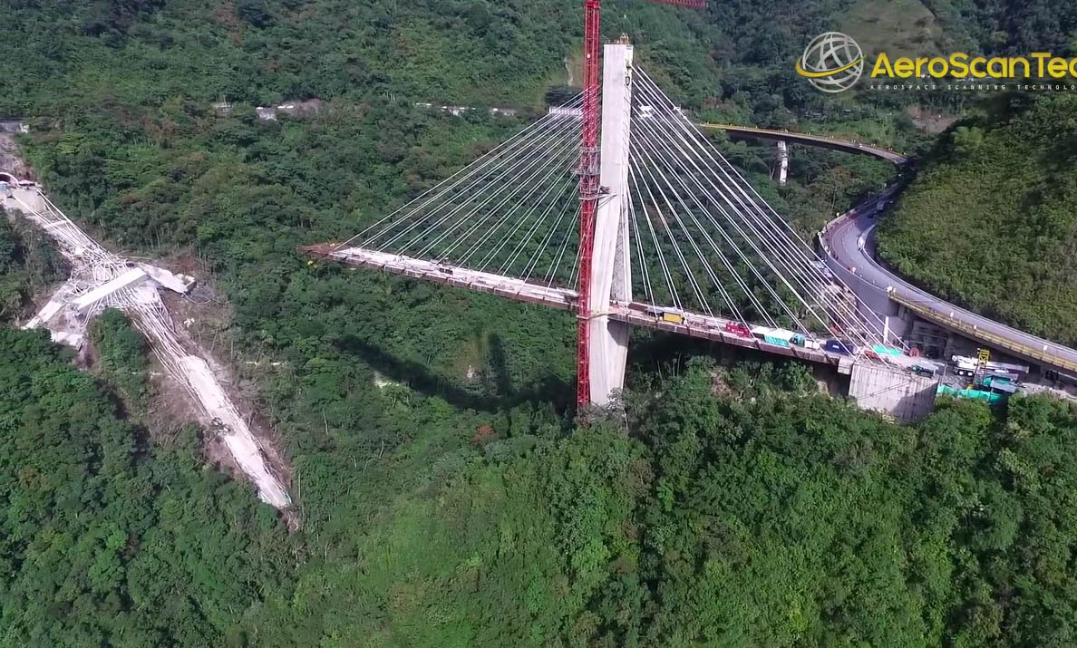
On January 15, 2018, the entire west side of the nearly finished Chirajara Bridge collapsed into the gorge killing 9 construction workers. After an investigation, engineers discovered that the horizontal connection within the diamond-shaped towers was insufficiently designed with a minimal number of prestressing cables. Incorrect calculations were also made about the lateral strength of the concrete diaphragm wall that connected the lower V-shaped legs of the towers. The study of the bridge collapse is detailed in an excellent IABSE paper written by Dr. Christos T. Georgakis, Dr. Yozo Fujino, Siegfried Hopf, Klaus H. Ostenfeld and Dr. S. Eilif Svensson.
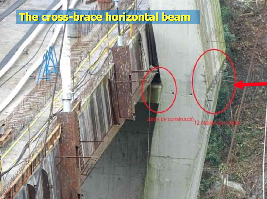
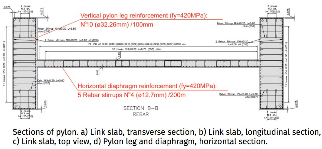
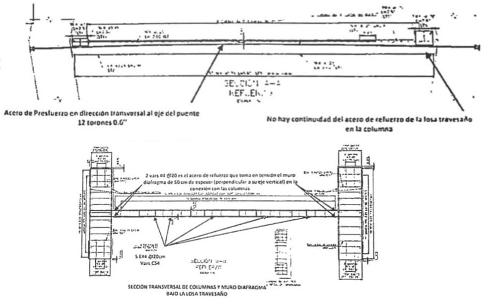
Normally the cross tie beams in a concrete cable stayed bridge tower are at least 2 meters thick with several rows of prestressing cables. For the Chirajara Bridge the cross tie was just .6 meters thick with only one row of 12 prestressing cables holding the two sides of the tower together.
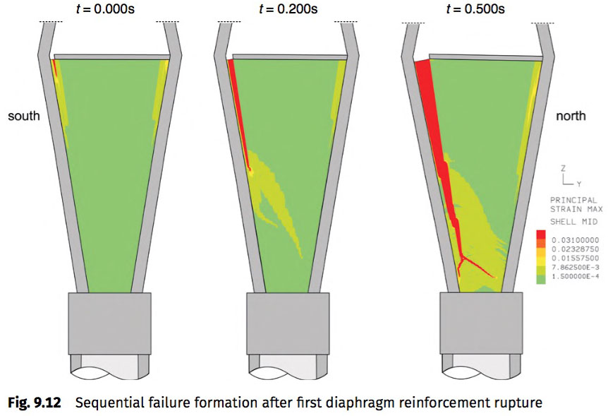
Although many of the world's cable stayed bridges have giant concrete wall "diaphragms" below the cross tie, rarely are they used to restrain the lateral tension of the tower legs. The Chirajara Bridge engineer assigned #4 rebar stirrups vertically every 20 cm within the diaphragm which was not nearly strong enough to counter the load path change between the upper A-shape columns of the tower and the lower V-shape columns that focus the weight of the bridge down into the narrow foundation pad.
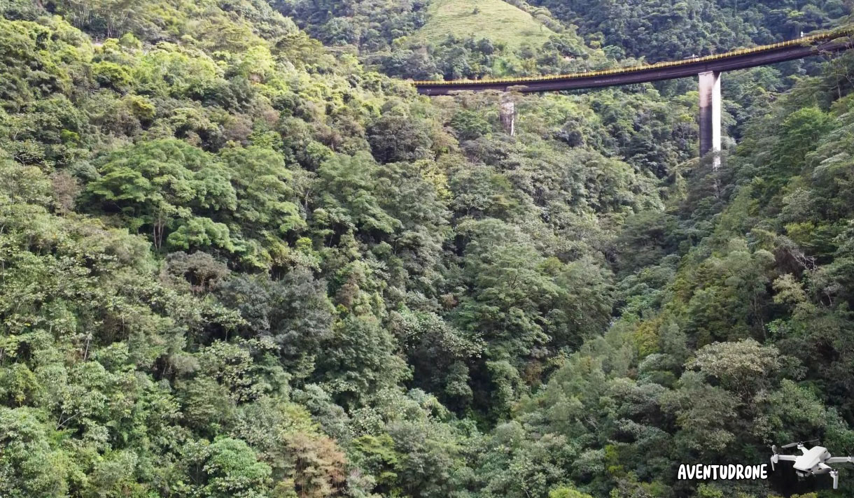
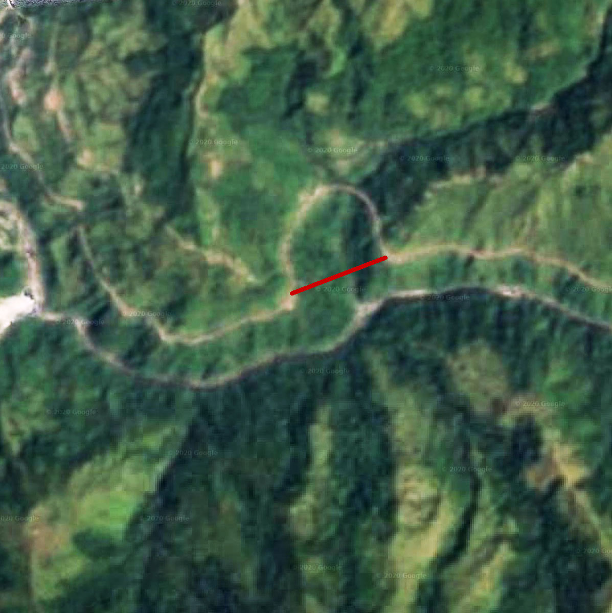
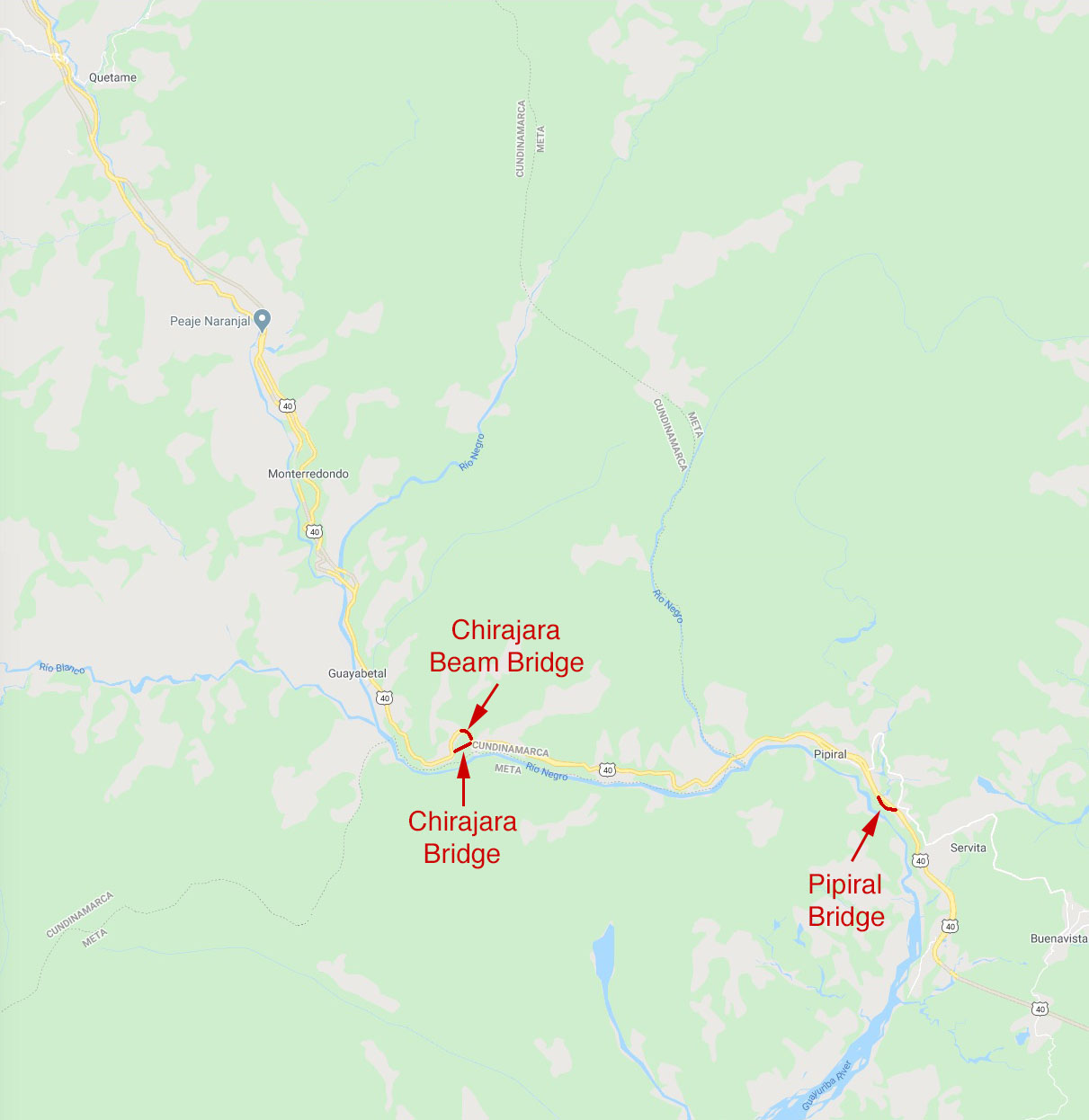
The older Chirajara Beam Bridge from 1995 still carries eastbound traffic and crosses 90 meters over Chirajara creek.
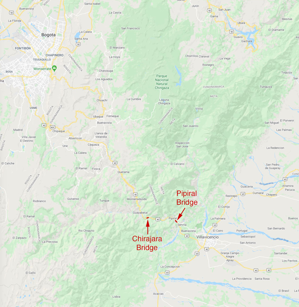
Completed in 2002, the 122 meter high Pipiral Bridge is the second highest span along the Bogota-Villavicencio route and is located about 10 kilometers to the east of Chirajara.
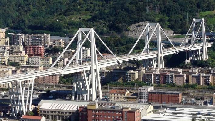
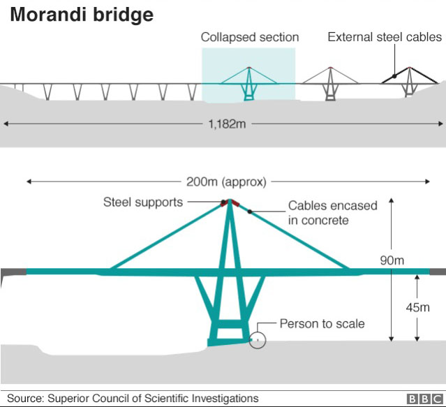
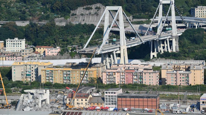
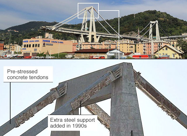
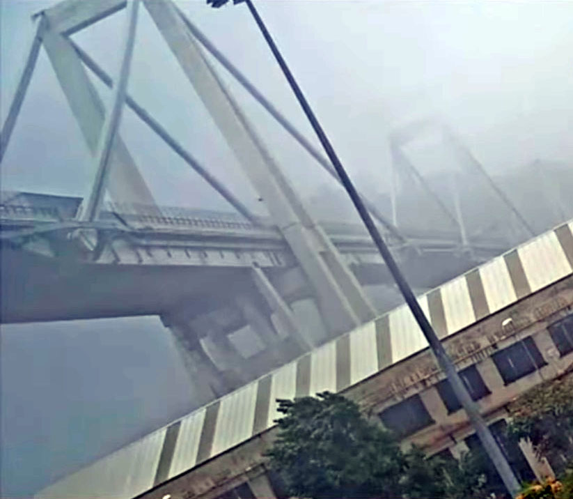
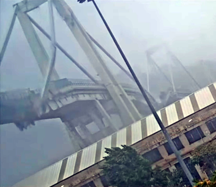
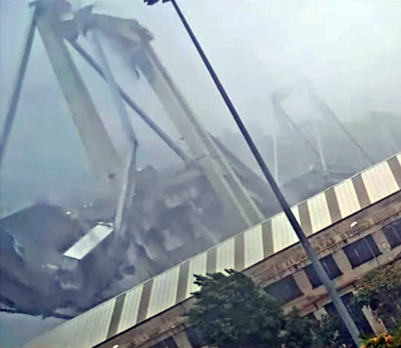
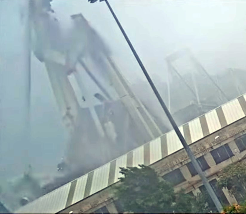
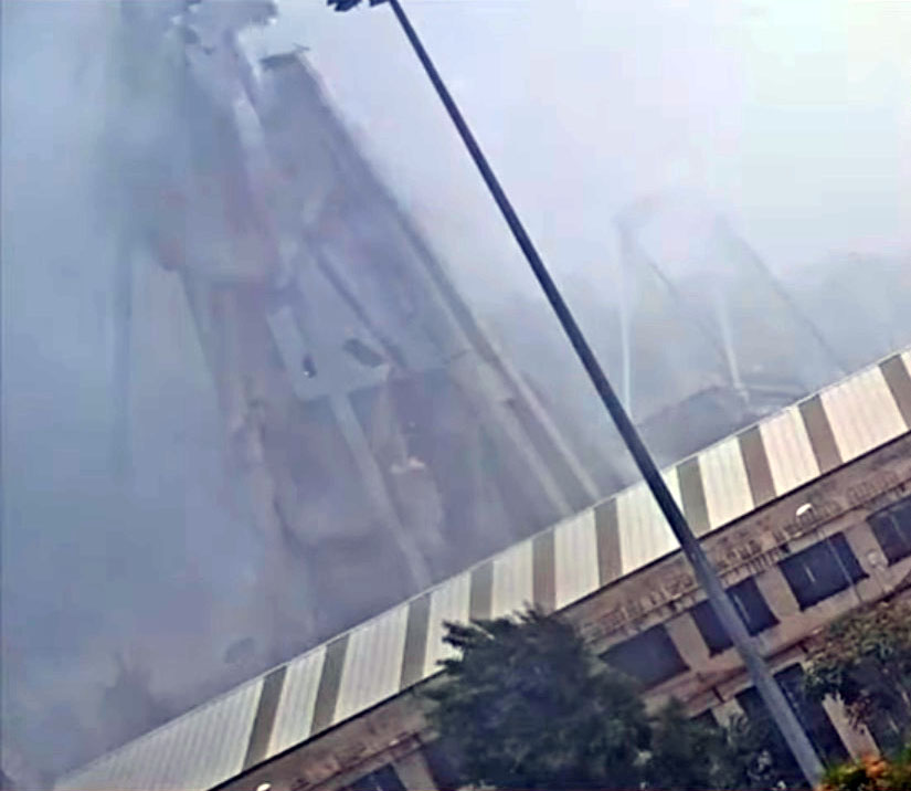
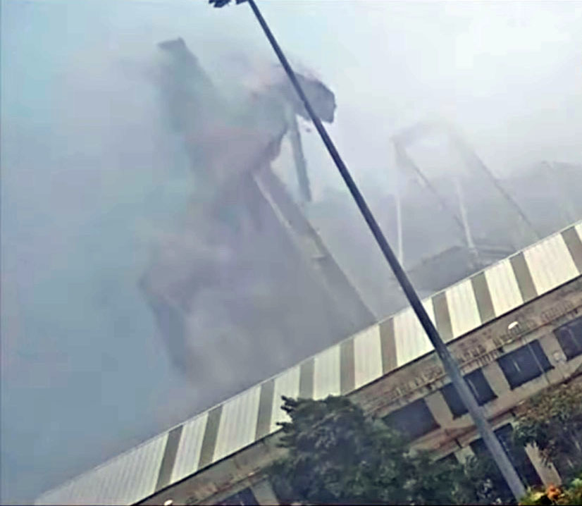
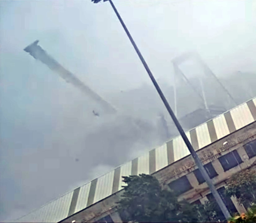
Sadly the Chirajara Bridge disaster would not be the last cable stayed accident in 2018 as on August 14 a tower and span of the Morandi cable stayed bridge in Genoa, Italy collapsed from excessive corrosion of the wire stays.
CHIRAJARA CABLE STAYED BRIDGE CRITICAL DEFICIENCIES
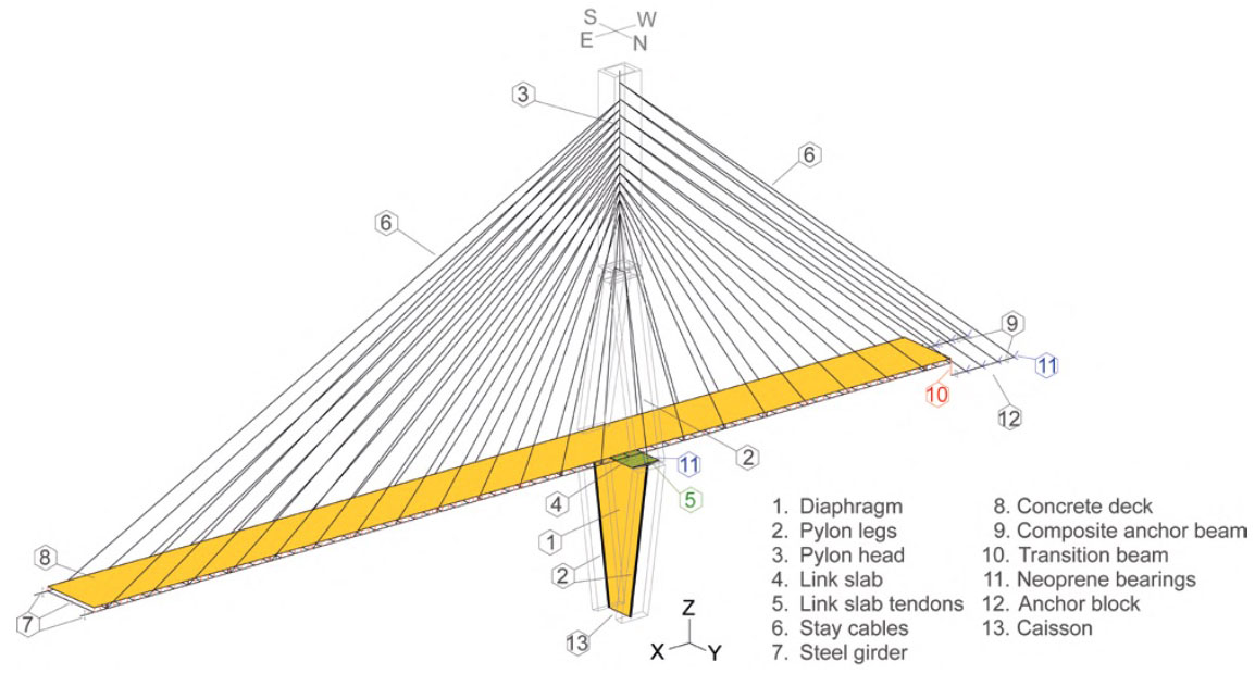
1. A severe lack of bracing tie capacity of the link slab and diaphragm was found for design loads, service loads, and during erection. The lack of bracing was the main deficiency leading to the eventual collapse of Pylon B and the bridge as a whole.
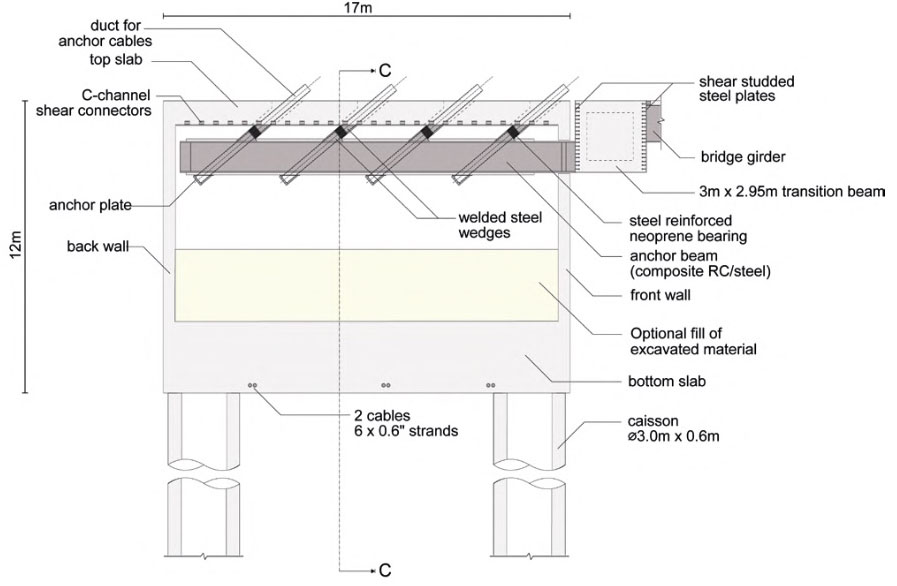
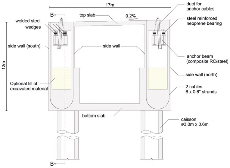
2. The bearing layout at pylons and abutments would result in a “floating” statical system. An unproven solution that among other things would induce large stresses in parts of the structure with incomplete direction and without respect for the flow of forces in the complete system. The bearings would not have sufficient capacity to withstand the expected shear forces and deformations during construction and for the service stage design loads, resulting in excessive shear deformations with potential failure.
3. Considerable redesign and retrofit of the anchor beam assembly would be needed to accommodate the design loads in the service stage. Deficiencies were found regarding the formation of local plastic hinges resulting in instability, insufficient lateral reinforcement at top face, and missing shear connectors between steel I-beams and encasing concrete to provide composite action. Most importantly, the bearing design related to the transition beam would need a complete redesign.
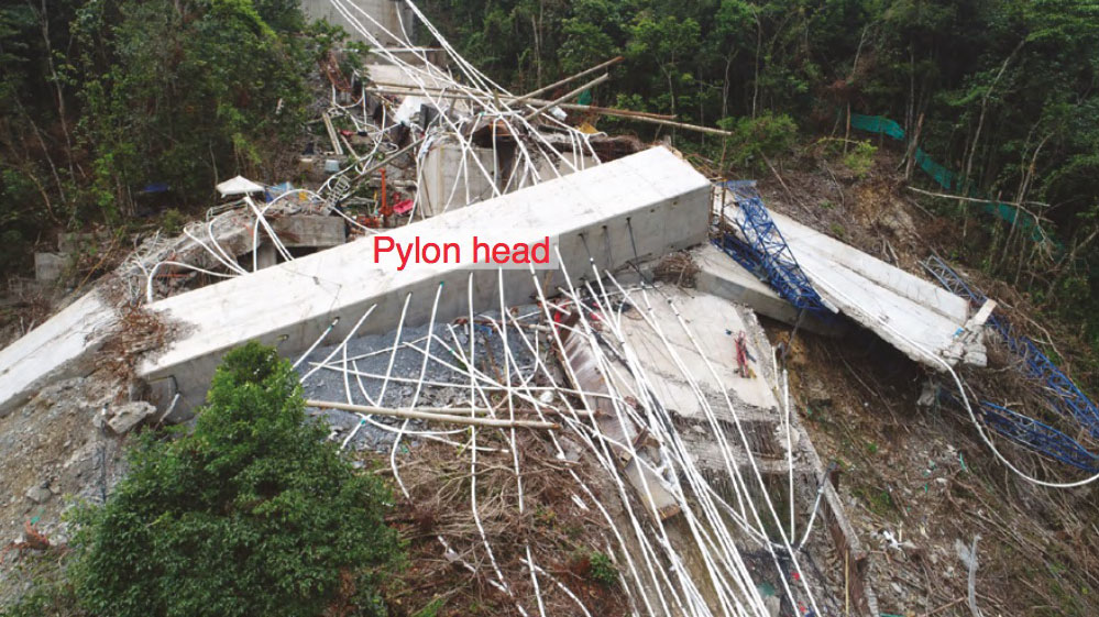
4. Longitudinal force components would create bending and high local shear stresses in the front and back wall of the pylon head since no bracing with sufficient shear capacity was provided inside the pylon head to transfer horizontal and vertical components of stay forces to the pylon head concrete walls.
5. The transition beam and corresponding connections were found to be inadequate and not designed with proper tensile capacity.
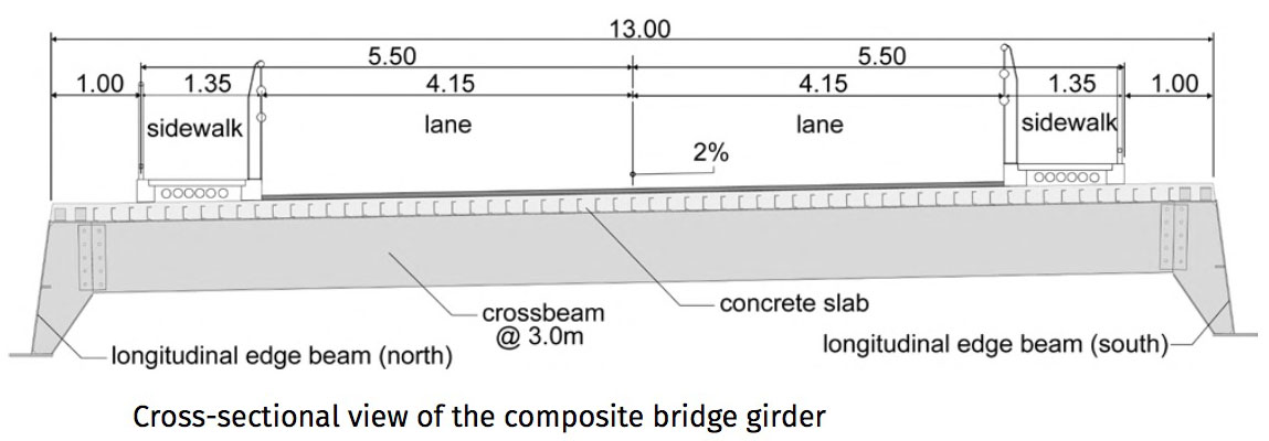
6. As designed, the longitudinal edge beams of the girder would experience a significant exceedance of allowable stresses in the bottom flange, due to negative bending at the pylon supports for service stage design loads. Overstress in the top flange was found at mid-span for transverse bending moments caused by design wind loads at service stage. Shear resistance of the web was found to be insufficient, and the web would be prone to buckling instability, even with the provided stiffening.
7. A lack of reinforcement was found in the longitudinal direction for the girder concrete slab, in regions with large negative moments. The specified transverse reinforcement was insufficient when considering transfer of shear between steel girder and concrete slab.
CHIRAJARA CABLE STAYED BRIDGE SECONDARY DEFICIENCIES
1. Sufficient structural capacity during construction and for service loads was found for the caisson. A slight excess of shear capacity was found for design loads. This could be rectified by applying actual material strengths instead of considering design values.
2. The elastic capacity of the girder cross beams would have been exceeded for service stage design loads.
3. Bolted connections in the girder would not comply with 75 %-capacity of connecting materials according to AASHTO.
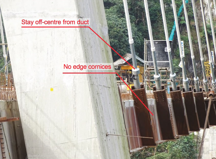
4. The girder section as erected was considered aerodynamically unstable and would be very prone to vortex shedding excitation. Proposed baffles and cornices were not installed during erection.
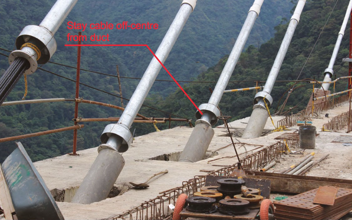
5. The varying transverse inclination of stay cables combined with the constant inclination of anchorage boxes at girder level could lead to bending of the cables at the point of attachment and/or local deformation of the steel beams.
New Chirajara Bridge render.
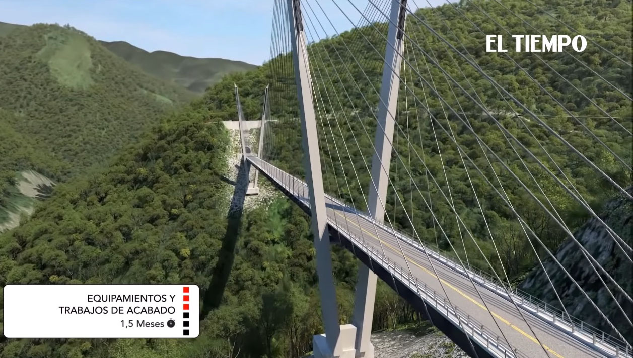
V-shaped cable stayed design that was to replace the collapsed bridge.
Original Chirajara Bridge render with the diamond shaped towers.
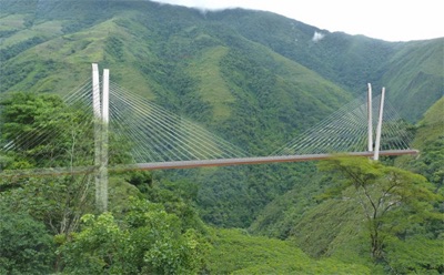
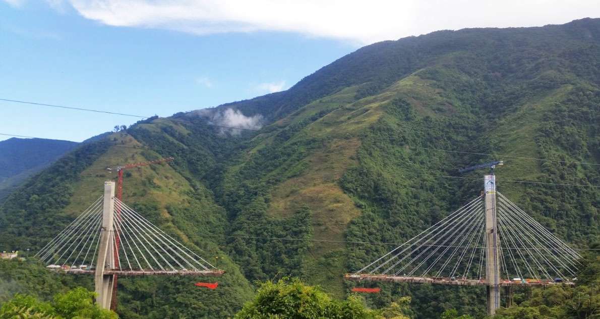
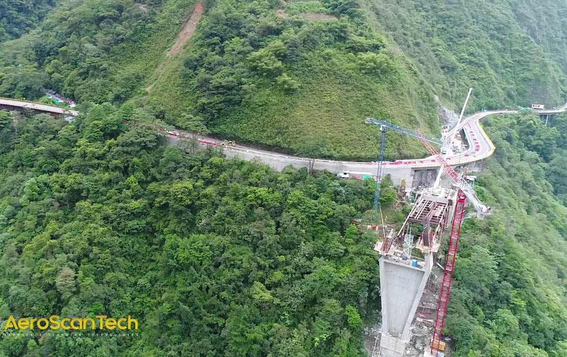
Old Chirajara Bridge under construction in 2018.
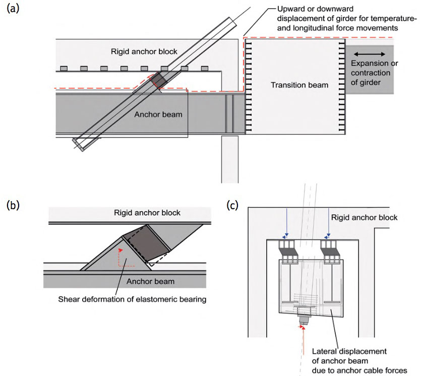
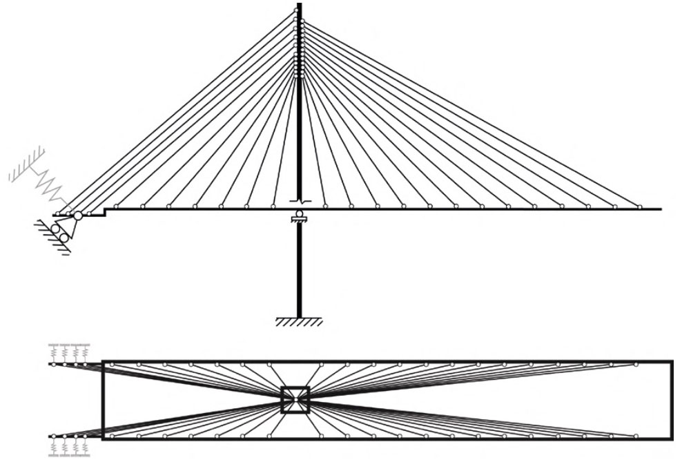
According to the IABSE report, equilibrium of the structure in both longitudinal and lateral direction was achieved through elastic support via deformation of the elastomeric bearings, as no rigid supports, or anti-lifting devices were provided between the girder and the substructure. This resulted in a somewhat “floating” statical system leading to excessive displacements for both the service and collapse stages. Generally, the displacements found at the bearings exceed those allowable in both the longitudinal and lateral directions. For service stage loads, it could be expected that some of the bearings would have sheared off.
Expansion, contraction or longitudinal movement of the girder, e.g., due to temperature deviations and breaking forces, would have led to deformation of the elastomeric bearings in shear as well. Because of the inclination of the bearings, this would have resulted in an upward or a downward displacement of the girder. Hence, these displacements would have led to the girder no longer being level with the rigid abutment. In addition, it was found that lateral (transverse to the bridge axis) displacements of the anchor beam would have been caused by the lateral component of the anchor cable force.
The anchor beam was only supported against the top slab of the anchor block by inclined elastomeric bearings. Besides excessive deformation of these elastomeric bearings, further deficiencies were found regarding the general flow of forces at the abutment. Deficiencies related to the connection between the longitudinal steel beams of the girder and the end plate, connected to the transition beam by shear studs, were identified. In addition to the axial force in the girder, induced by the unbalanced main span, bending moments were identified in the connection between the longitudinal steel beams and the transition beam. The identified bending moments at this point exceeded the bending capacity of the longitudinal edge steel beam of the girder for service stage loads.
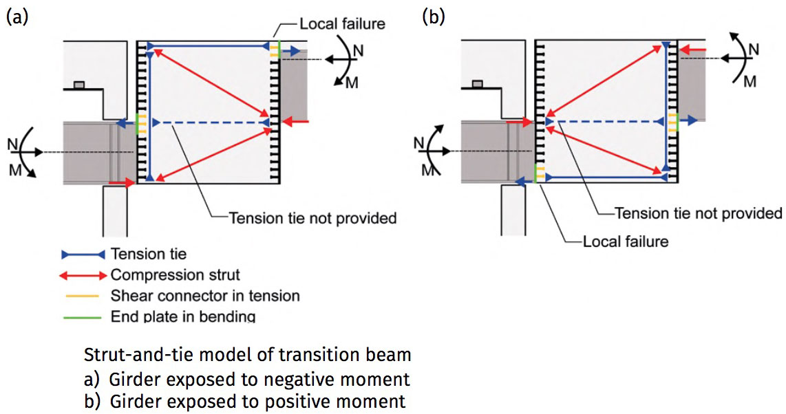
Furthermore, no reinforcement went through the connection between the girder and the transition beam. Hence, the entire tension force, introduced from the bending moment at the end of the girder, would have to be transferred through the endplate and the shear studs into the transition beam. However, the embedment length of the provided shear studs was insufficient to properly transfer these tensile forces, which eventually would have pulled out the studs. Also, it was found on site that the shear connectors consisted of bolts with threaded ends, welded to the steel plates. Welding of bolts would in general be considered unacceptable for any type of connection, as the tensile capacity of such a connection would be close to zero and the shear capacity undefined.
The transition beam itself was not designed properly for the high bending girder end moments. Deficiencies related to the transition beam were identified by a simple strut and tie model. The transition beam was only provided with reinforcement at the surface even though a tension tie would be required at the inner part of the concrete block. This, regardless of positive or negative moment in the connection between the longitudinal steel beam and the transition beam. These deficiencies were confirmed from site visits, where vertical crack formations at the bottom lower corner of the transition beam were identified.
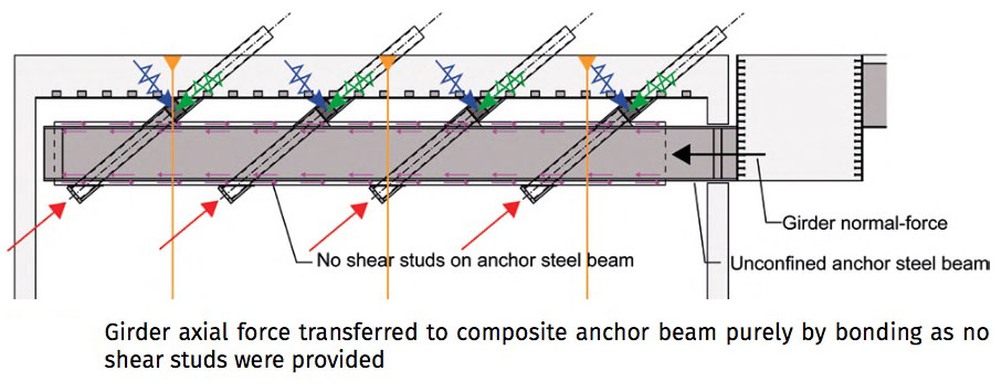
The anchor steel beams were not provided with any shear studs. Thus, the axial force, transmitted from the concrete transition beam into the “composite” anchor beam, would have to be transferred from the unconfined anchor steel beam to the concrete, purely by friction of bond between steel and concrete. Such a solution would be considered inadequate as pure steel against concrete exhibits rather poor bonding, resulting in a deficient composite effect.
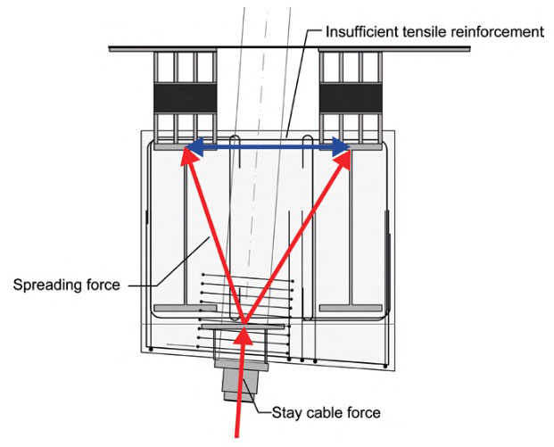
Insufficient tensile capacity at the top face of the anchor beam was found. The concentrated compression force, introduced by the anchor cables, must spread out into the two supports at the top of the beam. The provided reinforcement at the top was insufficient to carry the tensile forces, induced by this spreading.
Deficiencies were identified relating to the anchor beam at the abutment. Wind loads and other lateral forces acting on the girder, combined with the horizontal component of inclined stay forces directed inwards, would introduce local bending in the anchor beam. This would have been critical at the connection to the transition beam, where no reinforced concrete encased the I-steel beams of the anchor beam. Edge stresses above the elastic limit were found for service stage loads. This would lead to formation of plastic hinges at the end connecting to the transition beam and eventually also at the end where the anchor beam was covered in concrete. The formation of double plastic hinges would lead to instability and failure of the connection due to the column effect at service stage loads.
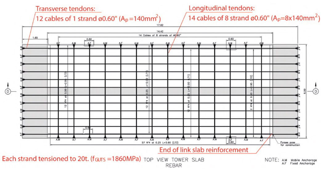
The IABSE report stated that the diaphragm, between the pylon knees, was a 0.6m thick link slab, extending the entire 6m width of the pylon legs along the bridge axis. The link slab was post-tensioned in both longitudinal (along bridge axis) and transverse (knee to knee) 2 directions. 14 tendons each consisting of 8 strands 0.6"in diameter (nom.A =140 mm), were provided in the longitudinal direction of the bridge. 12 tendons each consisting of a single 0.6" strand were provided as ties between the knees of the pylon in transverse direction and anchored within the pylon legs.
Horizontal reinforcement in the link slab was provided at the top and bottom faces by N°4 (⌀12.7mm) bars per 250mm in both longitudinal and transverse directions. The reinforcement ended at the edge of the link slab. No reinforcement, other than the 12 single strands, was provided between the link slab and the pylon legs.
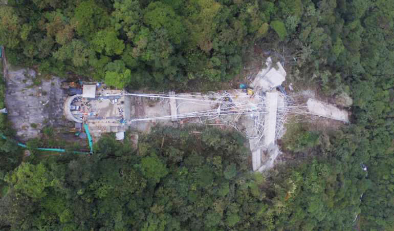
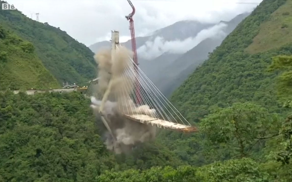
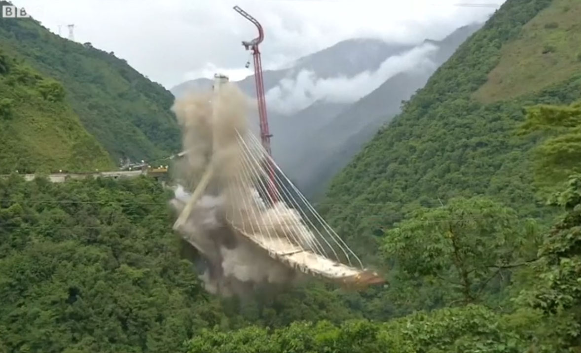
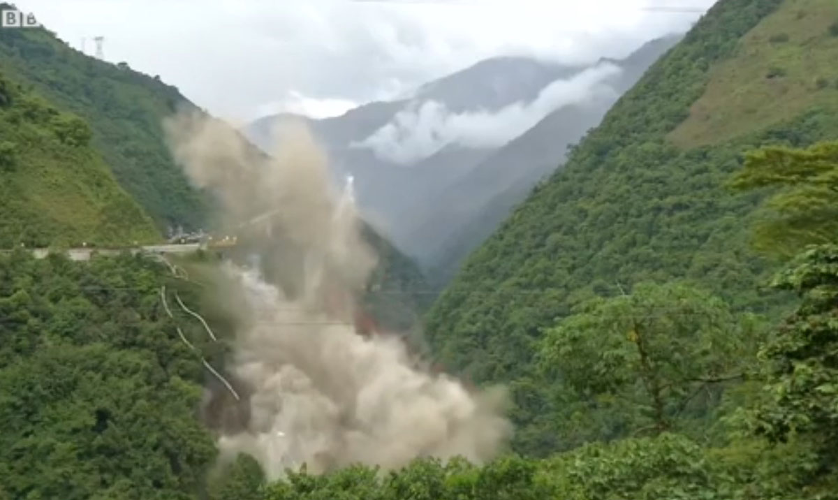
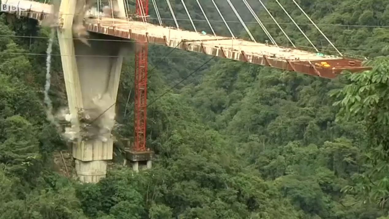
Implosion of East Tower of Chirajara Bridge on July 11, 2018.
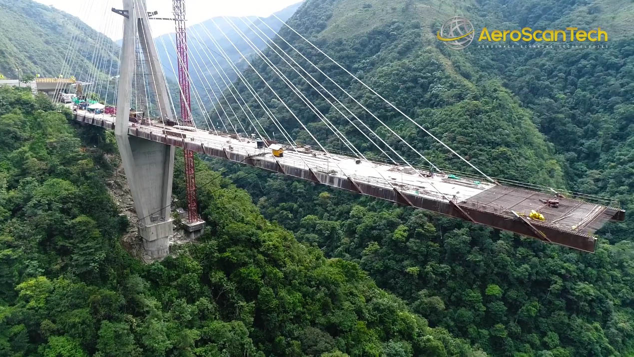
Early construction view before the collapse.
Chirajara Bridge satellite image.
Chirajara Bridge location map.
MORANDI BRIDGE COLLAPSE
On August 14, 2018 one of the three towers and two of the spans of Italy's Morandi Bridge collapsed in the city of Genoa. Years of corrosion from salty ocean air and factory pollution caused the steel tendons in one of the large concrete stays to snap. Unlike most cable stayed bridges that have several stays, the Morandi Bridge had only one set per span so there was no redundancy. The cantilevered design did not allow for the towers to support the weight of just one opposing span without bending or overturning.
Image by Luca Zennaro.
Image by AFP.
